Xilinx Programmable Logic Device Design and Development (Basic) Serial 50: Spartan
12.7 PicoBlaze Design Example
First, the design requirements 1. PICOBLAZE embedded system, including an 8-bit square wave output, one output for driving two 7-segment LEDs, one clock input and one interrupt input.
2. Implemented in the Spartan-3an starter kit.
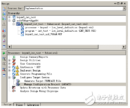
1. Create a new project in ISE 11.x, the project name is kcpsm3_int_test, and add the source file kcpsm3.vhd, this is just a PicoBlaze controller kernel file, readers can choose different design languages ​​according to their own preferences.
2. Write the assembly language source program of PicoBlaze. The assembly source program in this example is int_test.psm, as follows.
Interrupt example
;
CONSTANT waveform_port, 02 ; Define square wave output port ID is 02
CONSTANT counter_port, 04 ; Define interrupt counter output port ID is 04
CONSTANT sel_port, 08 ; Define 2-bit 7-segment LED selection output port ID is 08
CONSTANT pattern_10101010, AA ; Define the square wave output initial value
CONSTANT ini_sel, 01 ; Define 2-bit 7-segment LED bit selection initial value is 01
NAMEREG sA, interrupt_counter ; rename sA hosting to interrupt_counter
;
Start: LOAD interrupt_counter, 00 ; interrupt count register is cleared
LOAD s2, pattern_10101010 ; load square wave data into register s2
LOAD sD, ini_sel ; load the bit value into register sD
ENABLE INTERRUPT ; enable interrupt
;
Drive_wave: OUTPUT s2, waveform_port ; output square wave
OUTPUT sD, sel_port ; output LED bit selection
LOAD s0, FF; delay
Loop3: LOAD s1, FF
Loop4: SUB s1, 01
ADD s1, 01
SUB s1, 01
JUMP NZ, loop4
SUB s0, 01
JUMP NZ, loop3
XOR s2, FF ; square wave value inversion
XOR sD, FF ; bit selection value is reversed
JUMP drive_wave
;
ADDRESS 2B0; define program storage address
int_rouTIne: ADD interrupt_counter, 01; interrupt counter plus 1
OUTPUT interrupt_counter, counter_port ; output count value
OUTPUT sD, sel_port ; output bit selection
LOAD sF, FF; delay
Loop1: LOAD sE, FF
Loop2: SUB sE, 01
ADD sE, 01
SUB sE, 01
JUMP NZ, loop2
SUB sF, 01
JUMP NZ, loop1
XOR sD, FF
RETURNI ENABLE ; interrupt return
;
ADDRESS 3FF; interrupt entry address
JUMP int_rouTIne
3. Copy the int_test.psm file to the Assembler directory, run the DOS command, and enter
As the Assembler directory, run the following command:
Kcpsm3 int_test.psm > screen Enter
Some new files are generated in the Assembler directory after compilation, as shown in Figure 12-30. The INT_TEST.VHD/INT_TEST.V file is the file we need, it is the program memory file of PicoBlaze, and it is added to the kcpsm3_int_test project. As you can see, the generated PROM file name is the same as the file name of the assembler source.

Figure 12-30 Assembler directory file after compilation
The screen file is a text file, and the compilation process is recorded in this file. If the source file has an error, the error message will be found in this file.
4. Create a top-level file. Complete the connection of the PROM file and the PicoBlaze core file in the top-level file. The top-level file is briefly described below.
Instantiate kcpsm3 and INT_TEST.
Initialize unused PicoBlaze input pins in_port and reset.
The extended output registers are waveforms, counter, and sel, with port IDs of 0x02, 0x04, and 0x08, respectively.
Interrupt input logic.
The result of the counter is decoded into the input code of the 7-segment LED.
The top file source code is as follows.
--
Library IEEE;
Use IEEE.STD_LOGIC_1164.ALL;
Use IEEE.STD_LOGIC_ARITH.ALL;
Use IEEE.STD_LOGIC_UNSIGNED.ALL;
--
-------------------------------------------------- -----------------------
enTIty kcpsm3_int_test is
Port ( LED : out std_logic_vector(6 downto 0);
Waveforms : out std_logic_vector(7 downto 0);
Interrupt_event : in std_logic;
Ck : in std_logic;
Selp : out std_logic);
End kcpsm3_int_test;
-------------------------------------------------- -----------------------
Architecture Behavioral of kcpsm3_int_test is
--
Component kcpsm3
Port ( address : out std_logic_vector(9 downto 0);
instrucTIon : in std_logic_vector(17 downto 0);
Port_id : out std_logic_vector(7 downto 0);
Write_strobe : out std_logic;
Out_port : out std_logic_vector(7 downto 0);
Read_strobe : out std_logic;
In_port : in std_logic_vector(7 downto 0);
Interrupt : in std_logic;
Interrupt_ack : out std_logic;
Reset : in std_logic;
Ck : in std_logic);
End component;
--
Component int_test
Port ( address : in std_logic_vector(9 downto 0);
Instruction : out std_logic_vector(17 downto 0);
Ck : in std_logic);
End component;
--
-------------------------------------------------- -----------------------
Signal address : std_logic_vector(9 downto 0);
Signal instruction : std_logic_vector(17 downto 0);
Signal port_id : std_logic_vector(7 downto 0);
Signal out_port : std_logic_vector(7 downto 0);
Signal in_port : std_logic_vector(7 downto 0);
Signal write_strobe : std_logic;
Best Selling Promotional Price 1600 DPI Wired Gaming Mouse For Computer For Apple Laptop
2. The ergonomic shape design plus scroll wheel with rubber and skin-friendly surface provide you the most comfortable feeling in hand for long time.
3. Easy and quick to use, no need to install extra drivers or software. Support USB: 2.0/3.0 port.
Gaming Mouse,Usb Wired Computer Mouse Game,Usb Wired Gaming,Wireless Mouse For Computers
MICROBITS TECHNOLOGY LIMITED , https://www.hkmicrobits.com