Xilinx Programmable Logic Device Design and Development (Basic) Serial 46: Spartan
12.2.4 PicoBlaze interrupt
We know that the PicoBlaze microcontroller only provides one interrupt input. If multiple interrupts are needed in the design, it can be implemented in logic in the FPGA. Figure 12-4 shows a simple interrupt connection diagram. When an interrupt occurs, the 2 output of the flip-flop outputs a high level. When the PicoBlaze responds to the interrupt signal INTERRUPT_ACK, the flip-flop 3 is high. The output is cleared and the external interrupt is undone.
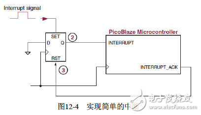
Figure 12-4 Implementing a simple interrupt
Next, we discuss the execution of the interrupt in conjunction with Figure 12-5 and Figure 12-6.
Figure 12-5 shows an interrupt routine that first enables the interrupt with the ENABLE INTERRUPT instruction. Once the interrupt is enabled, the interrupt signal must be asserted for at least 2 clock cycles to ensure it is recognized by PicoBlaze. When an interrupt event occurs, a valid interrupt causes PicoBlaze to jump to 3FF immediately after executing the currently executing instruction (INPUT s1, 01) to continue executing the instruction. Usually, 3FF is a jump instruction (JUMP isr) that jumps to the interrupt service routine. The interrupt service routine automatically disables the interrupt and saves the current PC value, ZERO and CARRY flags. When the interrupt service routine is executed and the interrupt service routine is exited, the RETURNI instruction is executed. The PC value temporarily stored in the CALL/RETURN stack is automatically loaded into the PC register. At the same time, the ZERO and CARRY flags are restored, and the program returns to the pre-interruption. The instruction is executed.
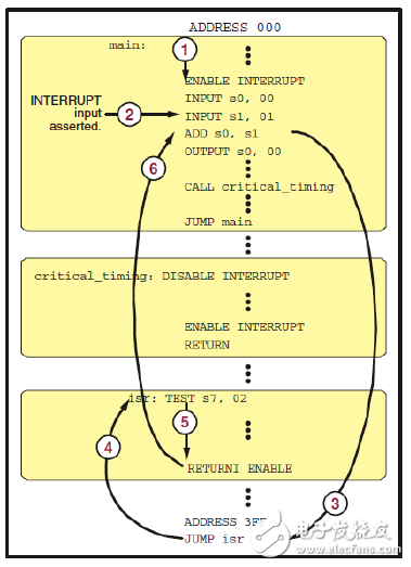
Figure 12-5 Interrupt flow <./center>
The execution of this interrupt can be clearly seen in Figure 12-6.
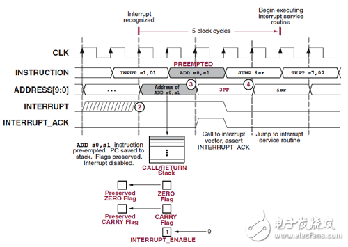
Figure 12-6 Interrupt timing diagram
If the application does not require an interrupt, INTERRUPT can be tied low and all 1024 instruction spaces can be accessed.
When applying the PicoBlaze interrupt, there are the following points to note.
• If the instruction space is not 1K, the PC will jump to the last instruction in the program space when the interrupt occurs.
• When the program enters the interrupt service routine, the microcontroller automatically disables all interrupts. When exiting the interrupt service routine, the interrupt is enabled with the RETURNI ENABLE instruction.
• In time-critical designs, use DISABLE INTERRUPT and ENABLE INTERRUPT to avoid unnecessary interruptions, such as the criTIcal_TIming subroutine shown in Figure 12-5.
12.2.5 PicoBlaze Scratchpad RAM - Register
The PicoBlaze microcontroller contains a 64-byte scratchpad that is accessed by the STORE and FETCH instructions to transfer data between the data registers and the scratchpad. Support for direct and indirect addressing. The scratchpad is only supported by Spartan-3/3E/3A/3AN, Virtex-II, Virtex-II Pro FPGA and Virtex-4/5/6. Reset does not affect the scratchpad.
First, the addressing mode(1) Direct addressing.
The immediate value is the address of the scratchpad, as shown in Figure 12-7, the register sX directly reads/writes the scratchpad.
(2) Indirect addressing.
The address of the scratchpad is the value of a specified register. The code shown in Figure 12-8 is used to fill all 64 scratchpad spaces with 0s.
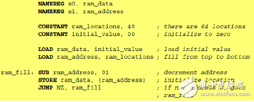
Figure 12-8 Indirect Addressing Register
Second, use the scratchpad to implement the lookup tableThis example uses a scratchpad to implement a lookup table that converts a 4-digit binary input to an equivalent hexadecimal character for display on a 7-segment LED. This code reads the external 4-bit switch and produces a binary result 0000~1111, which is converted to a hexadecimal character and displayed on the 7-segment LED. The first 16 positions in the scratchpad store the LED character table, and the input switch quantity is used as the address of the scratchpad. As shown in Figure 12-9.
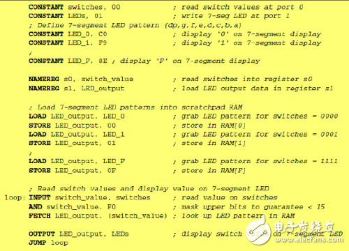
Figure 12-9 Scratchpad implementation lookup table
Third, use the scratchpad to achieve the stackIn PicoBlaze, although there is a CALL/RETURN program stack, there is no data stack. If you need to temporarily store some data during program call or interrupt processing, you need a data stack. In this case, you can use the scratchpad to implement this function. As shown in Figure 12-10.
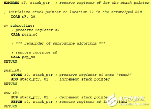
Figure 12-10 Scratchpad implementation data stack
Fast Wireless Charger,Iphone Wireless Charger,Portable Wireless Charger,Best Wireless Phone Charger
wzc , https://www.dg-wzc.com