ROHM's latest driver technology for LED backlights
LED light sources have rapidly spread in many automotive applications. ROHM's efficient LED light source drive technology creates a broad lineup of LED drivers for taillights, backlights and headlamps. Here, you will be introduced to the LED driver for the backlight.
<Development of LED Drivers for Car Backlights>
In recent years, in the field of vehicle-mounted displays, in order to meet the requirements of hazardous substances, CCFL backlights using mercury are being rapidly replaced by LED backlights. In addition, various in-vehicle displays such as instrument panels, car navigation, audio display, and rear seat entertainment are developing in a diversified and large-scale direction. Under this trend, the demand for increasing the number of LED lamps and high brightness and high dimming rate is increasing. In order to meet this trend of increasing the number of LED lamps, ROHM will realize a high-voltage step-up DC/DC converter, a multi-lamp driving low-power LED, and a high-light-adjusting current driver circuit built into one. The chip expands the lineup of LED driver products.
Next, the LED driver BD81A34EFV-M for backlights developed by ROHM will be introduced.
The BD81A34EFV-M is roughly composed of three functional blocks: a DC/DC converter unit, a current driver unit, and a protection circuit unit (Fig. 1).
[Fig. 1] Block diagram of BD81A34EFV-M
As a driving of the backlight, first, a DC/DC converter generates a constant voltage. The output of the DC/DC converter is connected to the anode side of the LED of the panel, and a constant current is injected from the cathode side of the LED to the LED driver to cause the LED to emit light. To support low-power multi-lamp LED drivers, the number of LED channels (number of columns that can be connected) is designed to be four.
By controlling the switching duty cycle of the DC/DC converter, the output is level above the LED anode pin, which includes the portion of the LED segment that is linked to the current driver, that is, the VF generated by the LED, through the LED driver. The error amplifier performs feedback control so that the LED cathode pins (LEDs 1~4 pins) connected to the IC are 1.0V. Through the above control, the current driver section can keep the LED current constant. As the brightness adjustment of the panel, the output current has PWM-dimming (PWM dimming) function. The duty cycle of the LED current can be varied synchronously with the external PWM signal input. Not only that, the BD81A34EFV-M is also equipped with LED open circuit and short circuit fault protection, LED ground fault protection, DC/DC converter output overcurrent and overvoltage protection. The perfect protection circuit is very helpful to improve the reliability of the panel.
The DC/DC converter circuit and current driver circuit are introduced above. Next, the characteristics of ROHM's on-board LED driver---anti-flicker circuit are introduced in order.
<Buck-boost DC/DC converter>
In the face of vehicle-specific battery voltage fluctuations and diversified LED lights, it is difficult to perform LED flicker control and platform design in boost mode and buck mode, to meet the high reliability required by the market and shorten the development cycle. The balance is not easy. Therefore, in order to stably supply the DC/DC converter output voltage regardless of the battery voltage, the ROHM adopts a unique buck-boost method called "REGSPIC structure". The following describes the REGSPIC structure with two advantages over the SEPIC structure used in the general buck-boost mode.
1 Reduce external components
Figure 2 shows the circuit configuration of SEPIC and REGSPIC. As can be seen from Fig. 2, in the REGSPIC structure, there are fewer coils having the highest area occupancy, and it is possible to achieve miniaturization and cost reduction. In addition, the inductance is reduced and the efficiency corresponding to the loss of the coil can be increased.
[Figure 2] Circuit composition of SEPIC and REGSPIC
2 achieve high reliability
In the SEPIC structure of Figure 2, C1 operates like a charge pump for the output voltage, so Q1 needs to reach the DC/DC converter output voltage.
(VOUT) + The withstand voltage level of the battery voltage. On the other hand, in the REGSPIC structure, since the withstand voltage is higher than the DC/DC converter output voltage and the battery voltage, the REGSPIC structure is composed of a low-voltage component and is easier to control.
In addition, Q2 is not only used for buck-boost control, but also can be used as a switch for disconnecting the battery from the battery when it is short-circuited to an external component such as an LED anode or a diode. Therefore, it can protect the external components when an abnormality occurs, which helps to achieve more. High reliability. In the SEPIC structure, Q3 is used only as a switch to cut off the path to the battery.
<High dimming current driver>
In order to meet the trend of the development of automotive panels in the direction of high brightness, ROHM has completed the technical development of the high-definition LED driver BD81A34EFV-M. The following explains why a high brightness of the panel requires a higher dimming rate. Although the panel brightness can be higher, the minimum brightness level required is almost unchanged. Considering the low brightness of the output in the dark, such as the human eye does not feel tired, if the highest brightness (dimming rate 100%) is lower, even low dimming rate can output low brightness, but in recent years, the panel specification generally has the highest brightness. They are all very high, so high dimming is required for low brightness output.
In order to achieve high dimming rate, the BD81A34EFV-M uses ROHM's unique technology to improve the response performance of the current driver output LED. The LED current is switched on and off according to the external PWM input duty cycle. At this time, the current driver circuit is turned off when the PWM signal is low level, and the current driver circuit is turned on when the level is high, and the LED current is adjusted according to the time ratio of the ON/OFF section. It is ideal to have the input PWM and output current fully synchronized and the timing is consistent. As long as this can be achieved, high brightness can be achieved. In fact, a circuit delay is generated from the input of the PWM signal to the current output, and due to this delay, it is impossible to generate a pulse within the time width.
A current control amplifier is mounted in the current driver circuit. However, according to the conventional PWM dimming method, when the current driver circuit is turned off and on, the circuit delay of several μs is generated as the startup time of the internal amplifier. As the market demands for dimming higher and higher, this circuit delay can no longer be ignored. Therefore, the PWM dimming circuit on the ROHM minimizes the startup time of the amplifier, resulting in a higher dimming rate.
Specifically, as shown in FIG. 3, the current drive amplifier has a feedback circuit for LED current output and another feedback circuit.
[Figure 3] Feedback Circuit of Current Drive Amplifier
These two feedback paths are switched by the respective SWs. In the PWM=High (LED is ON) section, a feedback circuit for driving the LED current (Fig. 3 feedback circuit 1) is driven, and the LED current is injected from the LED pin. In the PWM=Low (LED is OFF) interval, another feedback circuit (Fig. 3 feedback circuit 2) is driven to generate current from the internal constant voltage VREG. By performing such control, although the LED current is turned off, the current drive amplifier is always in the driving state, and the LED current can be smoothly generated when PWM=Low→High. Since the current I2 of the feedback path 2 has been set to several μA, the power consumption increase of the circuit structure has reached a negligible level.
Figure 4 is a comparison of how the follow-up of the PWM signal changes when the LED current has a different feedback path from the output.
[Figure 4] Comparison of LED current followability with or without feedback circuit
In the absence of an additional feedback path, a delay time of approximately 10 μs is generated from the point of PWM=OFF→ON to the generation of the LED current. In contrast, there is almost no delay time when there is another feedback path, which can be followed by a PWM pulse width of at least 1 μs. Assuming that the PWM frequency is 100 Hz, if it is a pulse width of 1 μs, a dimming rate of 10000:1 can be achieved. In summary, the BD81A34EFV-M achieves a high dimming rate, which greatly contributes to the high brightness of the panel.
<DC/DC converter output voltage discharge circuit to prevent LED flicker>
The problem with the DC/DC converter output as the LED anode control LED is that LED flicker occurs when restarting from the OFF state of the DC/DC converter.
When the switching output of the DC/DC converter is turned off by inputting an OFF signal to the LED driver and a protection operation during abnormality detection, etc., there is a residual charge in the output capacitor. The residual charge is discharged by a resistor divider circuit (Fig. 5 ROVP1, ROVP2) for DC/DC converter output voltage feedback. However, the discharge time is as long as several seconds, and therefore, it is necessary to consider the case of restarting in such a charge residual state. In this case, the residual charge is discharged through the LED element, and then normal startup control is performed. This transient discharge is manifested by the flashing of the LED.
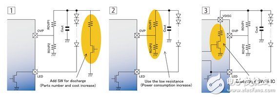
[Figure 5] Anti-LED flicker circuit
Traditionally, to prevent this flicker, one of the following two methods is generally selected. The first method is to add an external switching element to the DC/DC converter output as shown in Figure 5-1, and forcibly discharge when the circuit is OFF. This method can avoid flickering during restart, but requires the addition of switching elements and current limiting resistors, etc., and the number of components will increase.
The second method is to reduce the resistance value of the overvoltage protection as shown in Figure 5-2. Reduce the resistance value of the resistor divider circuit and promote the discharge of residual charge. The problem with this approach is that the power consumption during normal operation increases.
Therefore, as shown in Figure 5-3, the BD81A34EFV-M has an anti-flicker output discharge circuit built into the IC. This circuit allows the discharge of the output charge to be completed in just a few ms. Moreover, the number of external components and power consumption are not increased. For example, when the recommended values ​​of the external components of the BD81A34EFV-M are Cout=20uF, ROVP1=360kΩ, and ROVP2=30kΩ, set the DC/DC converter output voltage (Vout) to 30V.
No output discharge circuit: discharge time = about 7.8s
Output discharge circuit: discharge time = about 1.5ms
The discharge time can be greatly shortened and the resulting LED flicker can be prevented.
<future outlook>
In the future, high performance will be further developed. In this regard, ROHM will continue to promote the development of built-in communication functions and multi-channel LED drivers. Through the built-in communication function, different models can set different LED current, voltage, protection functions, etc. by communication. Each model does not need to create a drive circuit, which can promote platform development. In addition, by carrying the DiagnosTIc (diagnostics) function, it is possible to monitor the LED current and abnormal state in real time and feed it back to the microcontroller side, and it is possible to implement control suitable for different situations and improve the safety performance of the device. In addition, by multi-channel, the drive circuit for driving various lamps (DRL, turn signals, position lights, etc.) can be integrated into one IC, so that the number of channels required can be flexibly handled. ROHM will continue to develop high-performance ICs that meet customer needs and continuously develop ICs that contribute to automotive energy efficiency and high performance.
[About ROHM]
ROHM is one of the world's leading semiconductor manufacturers. Founded in 1958, it is a multinational group company headquartered in Kyoto, Japan. "Quality First" is Rom's consistent policy. We always put the quality of our products first. No matter how difficult it is, we will continue to provide a large number of quality products for domestic and foreign users, and contribute to the progress and improvement of culture.
After more than half a century of development, ROHM's production, sales and R&D networks are spread all over the world. Products cover a wide range of fields, including ICs, discrete components, optical components, passive components, modules, semiconductor applications, and medical devices. In the world electronics industry, many of Rom's high-quality products have been approved and praised by the market, becoming the leading company in system IC and the latest semiconductor technology.
ROHM attaches great importance to the Chinese market. It has established a number of representative offices throughout the country, established factories in Dalian and Tianjin, and has design centers and quality assurance centers in Shanghai and Shenzhen to provide technical and quality support.
[About ROHM's business development in China]
As a sales outlet in the Chinese market, Roma Semiconductor Hong Kong Co., Ltd. was first established in 1974. Subsequently, in 1999, Roma Semiconductor (Shanghai) Co., Ltd. was established. In 2003, Roma Semiconductor Trading (Dalian) Co., Ltd. was established. In 2006, Roma Semiconductor (Shenzhen) Co., Ltd. was established. In order to respond quickly and accurately to the requirements of the expanding Chinese market, Roma has built a one-stop system in China that integrates development, sales and manufacturing in the same way as Roma Japan. As a feature of ROHM, we are actively pursuing sales activities of “close to the customer†and strive to provide thoughtful services to our customers. Since the establishment of five inland areas in Xi'an, Chengdu, Chongqing, Wuhan and Changchun in the second half of 2010, there are currently 22 sales outlets in the country, including Hong Kong, Shanghai, Dalian and Shenzhen. Sales company and its 18 branches (branch: Beijing, Tianjin, Qingdao, Changchun, Nanjing, Wuxi, Suzhou, Hangzhou, Ningbo, Xi'an, Wuhan, Dongguan, Guangzhou, Huizhou, Xiamen, Zhuhai, Chengdu, Chongqing). And, the distribution network is gradually expanding.
As a technical base, we have design centers and QA centers in Shanghai and Shenzhen to provide technical and quality support. The design center is equipped with development and design support staff who are proficient in various markets, and can make technical proposals for customer needs in the form of integrated solutions from software to hardware. Moreover, when the product has a bad situation, the QA Center will respond to the appeal within 24 hours.
As a production base, in 1993, production plants were established in Tianjin (Rom Semiconductor (China) Co., Ltd.) and Dalian (Rome Electronics Dalian Co., Ltd.). Production of diodes, LEDs, laser diodes, LED displays, and optical sensors in Tianjin, power modules, thermal printheads, contact image sensing heads, image link modules, LED lighting modules, light sensors, and LED displays in Dalian Production, as the main production base of Roma, continues to provide high-quality products to China and abroad.
In addition, as part of the social contribution activities, ROHM is also committed to strengthening cooperation with many research institutions and enterprises at home and abroad, and actively promoting joint research and development activities of industry, academia and research. In 2006, it signed a joint industry-university framework agreement with Tsinghua University, and actively launched an industry-university alliance on the development of cutting-edge technology for electronic components. In 2008, the Tsinghua Rom Electronic Engineering Museum was donated in Tsinghua University and completed in April 2011. In 2012, Tsinghua University established the "Tsinghua-Rom Joint Research Center" and engaged in joint research projects such as "micro-energy devices, silicon emitters, biosensors, and digital broadcasting (demodulators) in China." In addition to Tsinghua University, Roma also cooperated with Xi'an Jiaotong University, University of Electronic Science and Technology, Zhejiang University and Tongji University to achieve fruitful results.
Based on the technical strength and high quality and reliability accumulated over the years, ROHM will build a solid partnership with customers through a solid technical support and customer service system integrating development, production and sales. Chinese companies make positive contributions to improving customer product strength, customer business development, and China's energy conservation and environmental protection.
Portable high efficient travel charger, can charge multi devices at the same time, every port output mini 5v 1a, max 5v 2.1a. We can meet your specific requirement of the products, like label design. The plug type is US/UK/AU/EU. The material of this product is PC+ABS. All condition of our product is 100% brand new.
Our products built with input/output overvoltage protection, input/output overcurrent protection, over temperature protection, over power protection and short circuit protection. You can send more details of this product, so that we can offer best service to you!
Usb Charger,Universal Travel Adapter,Intelligent Usb Charger,Travel Adapter
Shenzhen Waweis Technology Co., Ltd. , https://www.waweis.com