Application Research of Optical Fiber in Automotive Lighting System
0 Preface
With the advancement of science and technology and the improvement of people's living standards, automobiles have gradually become an indispensable tool for people's daily life. As an indispensable part of the safety performance of automobiles, automotive lighting has gradually evolved from simple night lighting to necessities that require beautiful appearance, safety, reliability, intelligence, comfort, energy conservation and environmental protection. At the same time, as a new carrier of optical transmission in the new century, optical fiber is widely used in communication, lighting and various kinds because of its non-conductivity, light weight, large capacity, high temperature resistance and electromagnetic radiation, good flexibility and convenient use. Sensing field. This article focuses on the various applications of optical fiber in automotive lighting systems with limited knowledge in personal learning and practice, and explores new directions and new areas in the development of automotive lighting technology.
1 basic principle and composition of optical fiber
Because light travels at different speeds in different materials, when light strikes from one substance to another, it refracts and reflects at the interface between the two substances. Moreover, the angle of the refracted light varies with the angle of the incident light. When the angle of incident light reaches or exceeds an angle, the refracted light will disappear and the incident light will be reflected back. This is the total reflection of light. Different materials have different angles of refraction for the same wavelength of light (ie different materials have different refractive indices of light), and the same material has different angles of refraction for different wavelengths of light. The optical fiber is a light-conducting carrier formed based on the principle that the core refractive index is greater than the cladding refractive index to form total reflection.
The optical fiber generally consists of three parts: a core, a cladding, and a coating layer (as shown in FIG. 1). Its materials can be broadly divided into two major categories of inorganic materials and organic materials III. The former has excellent light transmission performance, and the attenuation signal of the optical signal is small, and is suitable for long-distance optical information transmission, generally up to 100-200 km, but has high processing cost, strict quality control requirements, high brittleness, and easy breakage. Disadvantages; the acryl-based organic plastic fiber series has the opposite characteristics. It is soft and easy to connect, low in cost and easy to process. However, due to poor light transmission, the transmission distance is limited to 50 m. Generally only used for decoration and instrumentation. Considering the practical use and cost of automotive lighting, we generally use plastic optical fibers (POF) with a core diameter of 98 to 1 000 μm for automotive lighting.
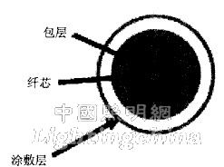
Figure 1 Fiber structure
2 Application of optical fiber in automotive lighting systems
Modern automotive lighting systems can be broadly classified into two broad categories: lighting devices and signaling devices. The lighting device is further divided into an exterior lighting device and an interior lighting device. The exterior lighting device is mainly designed to ensure the safety of the vehicle and improve the transportation efficiency. Different types of automotive lighting fixtures have strict regulations on the number of lights, installation location size, light color, power and light distribution performance in each country's regulations. The requirements in these regulations are automobile manufacturers and automobiles. Lighting factories must comply. For example, headlights, front fog lights, reversing lights and license plate lights; interior lighting devices are provided for the convenience of drivers and passengers, and there are no specific strict requirements for these lamps in the regulations of automobile lamps. Such as interior lights, instrument lights and luggage lights. Similarly, signal devices are also classified into in-vehicle signaling devices and off-board signaling devices. The off-vehicle signal device is designed to ensure the safety of the vehicle while driving, and is used to alert other drivers and pedestrians. For example, turn signal lights, brake lights, position lights and rear fog lights; the in-vehicle signal device is set for the driver, and the driver uses these signal devices to grasp the driving state of the car and understand the working conditions of the major systems of the vehicle. For example, far and near light indicators, turn indicators, fuel consumption warning lights, etc. (as shown in Figure 2). Each country has strict regulations on the color, graphic symbol, luminous intensity and working state of the signal device. These regulatory requirements are also mandatory for automotive manufacturers and automotive lighting and instrumentation plants.
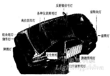
Figure 2 Automotive lighting system
As a new type of light guiding unit, optical fiber perfectly connects the light source with the automotive lighting system. The advantages are as follows: (1) Photoelectric separation. In the traditional automotive lighting system, the light source is directly converted from light energy into light energy, and light and electricity are inseparable. However, electricity has certain dangers, so many occasions want to separate light from electricity, eliminate various hidden dangers, and ensure the safety of lighting. Fiber optic lighting can achieve this, so that the light source and the lighting device are successfully separated, which not only facilitates the modular research of automotive electrical products, but also facilitates product replacement and maintenance;
(2) Flexible transmission of light. In theory, light is transmitted in a straight line. However, due to the diversity of practical applications, it is always desirable to be able to easily change the direction of light propagation. Fiber optic illumination meets this requirement, and the light beam output from the light source is delivered to a specified position according to its conduction path, and can be freely shaped according to the appearance requirements;
(3) A single light source may have a plurality of light-emitting points having the same light-emitting characteristics, and a plurality of light sources may be concentrated to a point to increase the light intensity;
(4) The system heat is lower than the general lighting system, so that the power consumption of the whole vehicle can be reduced;
(5) Green, safe, reliable and reusable.
2.1 Working methods and structure
A fiber optic automotive lighting system can be roughly divided into three parts: an illuminator, a light guide unit, and an output unit (as shown in FIG. 3). The illuminator consists of a light source, a mirror, and a color wheel (optional). The light source is located at the first focus of the ellipsoidal reflecting surface, and the emitted light is reflected by the mirror and concentrated at the second focus. The incident end of the fiber is placed at this point so that as much light as possible can be input into the fiber. Since the illuminant part of the light source has a certain geometrical size instead of a complete point source, the light source is reflected by the mirror and has a certain size image at the incident surface of the fiber. The size of the image depends on the light source, the mirror and the fiber incident. The distance between the faces. In order to make full use of the light, the position between the three must be chosen so that the image of the illuminant is smaller than the effective area of ​​the fiber, so that the light reflected by the mirror through the mirror can all enter the fiber. In addition, when designing the mirror, the solid angle formed by the light source should be as large as possible to receive as much light as possible, while ensuring that the incident angle of the reflected light coupled into the fiber is smaller than the numerical aperture of the fiber. At present, one of the most basic technical problems faced by the coupling unit is the thermal stress problem of the fiber optic human end. The radiation of the light source is mostly infrared. The light is focused on the incident surface of the fiber through the mirror. The fiber absorbs the infrared radiation. In addition, the fiber material itself inevitably contains impurities and has non-uniformity. The temperature at the incident end of the light can rise up to A few hundred degrees Celsius, resulting in severe thermal stress, causing damage to the fiber. In order to avoid this problem, one method is to place a filter between the mirror and the incident end of the fiber, which absorbs infrared radiation and absorbs less visible light, which greatly reduces the thermal effect at the incident end of the fiber. The downside of this approach is that the infrared blocking filter absorbs approximately 10% to 15% of the visible light, reducing the efficiency of the system. Another method is to use a cold-light coating on the mirror. The coating has a lower reflectance to infrared radiation and a higher reflectance to visible light. This method is better than the former method. A luminescence mirror made by selecting an appropriate interference film plated on a substrate has a higher reflectance for visible light than an aluminized mirror. The use of such a reflector maintains the temperature of the fiber optic end at a level below a certain critical temperature.
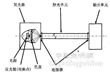
Figure 3 Optical fiber lighting system structure
Considering that the cross-sectional size of the received light of the fiber is limited and the incident angle of the received light of the fiber has a maximum angle, that is, the numerical aperture of the optical fiber to meet the requirement of total reflection during transmission, we usually have a plurality of plastics having a diameter of 98 to 1 000 m. The fiber bundles are composed of bundles of several millimeters in diameter and are bundled for use with several fixed output units. In this way, not only the utilization of light and the bending and impact resistance of the light guiding unit are improved, but also the complex light distribution is realized by using different positions of the respective guiding beams. In addition, the cross section of the fiber bundle output arm can also be made into different shapes as needed to meet different modeling requirements. In order to facilitate the installation, the fiber bundle can be reliably connected with the illuminator and the output unit, and the input and output ports of the fiber bundle are fastened with a metal ring (as shown in FIG. 4). 4.a is a threaded structure, that is, the connecting buckle is installed on the outer diameter of the docking device, and is fastened by the thread; 4.b is an external thread structure, that is, the connecting buckle is installed on the inner diameter of the docking device, and is fastened by the external thread. The difference between the two is that the former is convenient for docking, and the latter saves operating space.
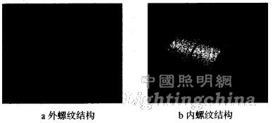
Figure 4 port connection structure