Inductive knowledge summary
 ·Inductor Top
 Dià ngǎn
[INDUCTORS] Circuits can produce electromotive force properties when the following current changes. Also refers to components made using this property What are inductors, transformers?
Inductors (inductors) and transformers are electromagnetic induction components that are wound with insulated conductors (such as enameled wire, yarn wrapped wire, etc.) and are also one of the commonly used components in electronic circuits. Related products include common-membrane filters, etc. .
One, self-inductance and mutual inductance
(I) Self-inductance When there is a current passing through the coil, a magnetic field is generated around the coil. When the current in the coil changes, the surrounding magnetic field also produces a corresponding change. This changing magnetic field can cause the coil itself to generate an induced electromotive force (the electromotive force is used to represent the terminal voltage of the ideal power source of the active element). This is the self-inductance.
(b) Mutual inductance When two inductors are close to each other, the change of the magnetic field of one inductor will affect the other inductor. This effect is mutual inductance. The degree of mutual inductance depends on the inductance of the inductor and the degree of coupling of the two inductors.
Second, the role of inductors and circuit graphic symbols
(1) Inductor's circuit pattern symbol Inductor is a set of serial coaxial coils made of enamelled wire, yarn wrapped wire, or plastic sheathed wire, etc. wound on an insulating skeleton or core or iron core. It uses letters in the circuit. "L" indicates that Figure 6-1 is its circuit graphic symbol.
(B) the role of inductors The main role of the inductor is to isolate the AC signal, filter or capacitor and resistors and other components of the resonant circuit.
Third, the role of the transformer and circuit graphic symbols
(A) Transformer circuit pattern symbol Transformer is made of components using the inductor's electromagnetic induction principle. In the circuit, the letter "T" (the old standard is "B") is represented, and its circuit graphic symbol is shown in Figure 6-12.
(B) the role of transformer Transformer is to use its primary (primary), secondary (secondary) windings between the number of turns (turns) ratio to change the voltage ratio or current ratio, to achieve electrical energy or signal transmission and distribution. The main functions include reducing AC voltage, increasing AC voltage, coupling signals, transforming impedance, and isolation.
(A) The structure and characteristics of the inductor The inductor is generally composed of skeleton, winding, shield, encapsulating material, magnetic core or iron core.
1. Skeleton skeleton refers to the coiled stent. Some large-sized fixed inductors or adjustable inductors (such as oscillation coils, choke coils, etc.), most of which enclose the enameled wire (or yarn wrapped wire) around the skeleton, and then the magnetic core or copper core, iron core, etc. Load the inner cavity of the skeleton to increase its inductance.
Skeletons are usually made of plastics, bakelite, and ceramics, and can be made into different shapes according to actual needs.
Small inductors, such as color code inductors, typically do not use a bobbin, but instead directly wrap the magnet wire around the core.
Hollow inductors (also called tire-out coils or air-core coils, which are mostly used in high-frequency circuits) do not use cores, frames, shields, etc., but first take off the mold and then take off the mold, and pull the coil between the circle A certain distance.
2. Winding winding refers to a group of coils with a specified function, which is an essential part of the inductor.
Windings have single and multiple layers. The single-layer winding has two types of tight winding (when the wire is wound by one turn and one winding around) and the inter-winding (when the winding is wound, each wire is separated by a certain distance); the multilayer winding has layered flat winding and chaos. Winding, honeycombing and other methods, as shown in Figure 6-5.
3. Magnetic cores and bar magnet cores and bar magnets generally use nickel-zinc ferrite (NX series) or manganese-zinc ferrite (MX series) materials, which have "work" shape, columnar shape, hat shape, "E" shape, Cans and other shapes, as shown in Figure 6-6.
4. Iron core materials mainly include silicon steel sheets, permalloy, and the like, and their shape is mostly "E" type.
5. In order to prevent the magnetic field generated by some inductors from affecting the normal operation of other circuits and components, some shields have been added to metal shields (such as the oscillating coils of semiconductor radios). Shielded inductors increase coil losses and reduce Q.
6. Packaging materials Some inductors (such as color code inductors, color ring inductors, etc.) are wound and sealed with a packaging material to seal the coils and cores. The packaging material is plastic or epoxy resin.
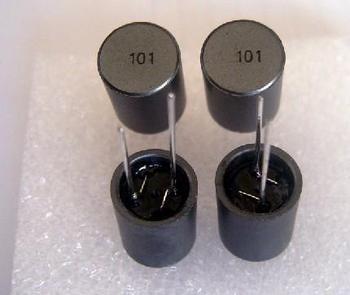
(B) Small fixed inductors Small fixed inductors are usually made by winding an enameled wire directly on a magnetic core. They are mainly used in circuits such as filtering, oscillation, notch, and delay, and they have both sealed and unsealed packages. In the form, both forms have two kinds of vertical and horizontal shape structures, as shown in Figure 6-7.
1. Vertical Sealed and Fixed Inductors Vertical Sealed and Fixed Inductors Adopt the same-direction pins, domestically produced series inductors such as LG and LG2, imported Jiebixin high-frequency inductors and Jiebixin power inductors, etc. The range is 0.1~2200μH (straight on the housing), the rated operating current is 0.05~1.6A, the error range is ±5%~±10%, the imported inductance, the current range is larger, and the error is smaller. TDK series color code inductors are imported, and their inductance is marked on the surface of the inductor by color dots.
2. Horizontal Sealed and Fixed Inductors Horizontal Sealed and Fixed Inductors adopt axial type pins and domestically produced series such as LG1, LGA and LGX.
The inductance of LG1 series inductors is in the range of 0.1~22000μH (straight on the housing), rated operating current is 0.05~1.6A, and the error range is ±5%~±10%.
The LGA series inductors are ultra-small and similar in appearance to 1/2W color ring resistors. The inductance range is 0.22~100μH (marked on the housing with a color ring) and the rated current is 0.09~0.4A.
The LGX series color code inductor is also a small package structure with an inductance range of 0.1~10000μH. The guage current is divided into four types: 50mA, 150mA, 300mA and 1.6A.
(3) Adjustable inductors commonly used for adjustable inductors include oscillation coils for semiconductor radios, line oscillation coils for televisions, line linear coils, mid-frequency notch coils, frequency compensation coils for acoustics, and wave-blocking coils, as shown in Figure 6. -8 shows.
1. An oscillation coil for a semiconductor radio This oscillation coil forms a local oscillation circuit in a semiconductor radio and a variable capacitor or the like for generating a local oscillation signal higher than 465 kHz for a station signal received by an input tuning circuit. The outer part is a metal shield cover, and the inner part is composed of a nylon lining frame, an I-shaped magnetic core, a magnetic cap and a pin seat and the like. On the I-shaped magnetic core, a winding with a high-strength enameled wire is used. The magnetic cap is mounted on a nylon frame in the shield and can be rotated up and down to change the inductance of the coil by changing its distance from the coil. The internal structure of the TV mid-frequency notch coil is similar to that of the oscillating coil, except that the magnetic cap can have an adjustable core.
2. Line oscillation coils for televisions are used in early black-and-white television sets, and they consist of self-oscillating circuits (three-point oscillators or intermittent oscillators, multivibrators) with external RC components and line oscillation transistors. Used to generate a rectangular pulse voltage signal with a frequency of 15625 Hz. The center of the magnetic core of the coil has a square hole, and the line synchronous adjustment knob is directly inserted into the square hole, and the line synchronous adjustment knob is rotated, the relative distance between the magnetic core and the coil can be changed, thereby changing the inductance of the coil and keeping the line oscillation frequency. For 15625Hz, synchronous oscillations are generated with the line sync pulses fed by the automatic frequency control circuit (AFC).
3. Linear Coil Row Linear Coil is a non-linear magnetically saturated inductor (whose inductance decreases with increasing sheep current). It is normally connected in series in the horizontal deflection coil loop and uses its magnetic saturation characteristics to compensate for linearity of the image. distortion.
The linear coil is made by winding an enameled wire on an "I" shaped ferrite high-frequency magnetic core or ferrite magnetic bar, and an adjustable permanent magnet is arranged next to the coil. By changing the relative position of the permanent magnet and the coil, the inductance of the coil is changed to achieve the purpose of linear compensation.
(D) The deflection coil The deflection coil is an accessory part of the television picture tube. It includes a horizontal deflection coil and a field deflection coil. They are placed on the neck (cone part) of the picture tube to control the scanning movement direction of the electron beam. The horizontal deflection coil controls the electron beam for horizontal scanning, and the field deflection coil controls the electron beam for vertical scanning. Figure 6-9 shows the outer shape and structure of the deflection yoke.
(5) The choke inductor The choke inductor refers to the inductor used to block the AC current path in the circuit. It is divided into high-frequency choke coils and low-frequency choke coils.
1. High-frequency choke coils High-frequency choke coils, also known as high-frequency choke coils, are used to block high-frequency alternating currents from passing through.
High-frequency choke coils work in high-frequency circuits. They use hollow cores or ferrites for high-frequency magnetic cores. The skeletons are made of ceramic materials or plastics. The coils are made of honeycomb-type segmented winding or multi-layer flat winding. See Figure 6-10.
2. Low-frequency choke coils Low-frequency choke coils, also known as low-frequency choke coils, are used in circuits such as current circuits, audio circuits, or field outputs, and their function is to prevent the passage of low-frequency alternating currents.
In general, a low-frequency choke coil used in an audio circuit is called an audio choke coil, a low-frequency choke coil used in a field output circuit is called a field choke coil, and a low-frequency choke coil to be used in a current filter circuit Known as a filter choke.
Low-frequency choke ring generally use "E"-shaped silicon steel core (commonly known as silicon steel core), permalloy iron core or iron oxide oxygen core. In order to prevent magnetic saturation caused by a large DC current, proper clearances should be left in the core during installation. Figure 6-11 shows the outer shape and structure of the low frequency choke coil.
(B), the structure and characteristics of the transformer (a) the structure of the transformer The transformer is generally composed of three parts of conductive materials, magnetic materials and insulating materials.
1. The conductive material of the conductive material transformer is mainly a variety of high-strength enameled wire, and only the tuner wire is used in tuning high-frequency transformers.
2. The magnetic materials used in magnetic material power transformers and low frequency transformers are mainly silicon steel sheets. The magnetic materials used in intermediate frequency transformers, pulse transformers, and oscillating transformers are mainly ferrite magnetic materials.
3. In addition to the skeleton, the insulating material of the insulating material transformer includes interlayer insulating material and impregnated material (insulating paint).
(B) The main purpose of the power transformer power transformer is to step up (raise the AC voltage) or step down (reduce the AC voltage), and the number of turns of the primary (primary) winding of the step-up transformer compared to the secondary (secondary) winding ( The number is small, and the primary winding of the step-down transformer has more turns than the secondary winding. Transformers used in regulated power supplies and various home appliances are buck power transformers.
Power transformers are divided into "E" power transformers, "C" power transformers and environmental pollution power transformers.
1. The core of the "E" power transformer "E" power transformer is formed by overlapping silicon steel sheets. The disadvantage is that the air gap in the magnetic circuit is large, the efficiency is low, and the electrical noise during operation is large. The advantage is that the body is inexpensive.
2. The core of the "C" type power transformer "C" type power transformer is formed by two identically shaped "C" type cores (made of cold-rolled silicon steel strips), compared with the "E" type power transformer. The air gap in the magnetic circuit is small and the performance is improved.
3. Ring Power Transformer The core of the toroidal power transformer is made of cold-rolled silicon steel strip. There is no air gap in the magnetic circuit, and the magnetic leakage is minimal. The electrical noise during operation is small.
Figure 6-14 shows the appearance of the power transformer.
(3) Low-frequency transformers The low-frequency transformers are used to transmit the signal voltage and signal power of the pounds, and can also realize the impedance matching between circuits and have an isolation effect on the direct current. It is divided into inter-stage coupling transformers, input transformers and output transformers, all of which are similar in shape to power transformers.
1. The interpole coupling transformer interstage coupling transformer is used between the two stages of audio amplifying circuits as a coupling element, and the output signal of the preamplifier circuit is transmitted to the next stage, and an appropriate impedance transformation is performed.
2. Input Transformer In early semiconductor radios, the transformer used between the audio driver stage and the power amplifier stage was an input transformer, which acted as a signal coupling and transmission, also known as a push transformer.
Input transformers have single-ended input and push-pull input types. If the push circuit is a single-ended circuit, the input transformer is also a single-ended input transformer; if the push circuit is a push-pull circuit, the input transformer is also a push-pull input transformer.
3. The output transformer of the output transformer is connected between the output circuit of the power amplifier and the loudspeaker, mainly acting as signal transmission and impedance matching.
Output transformers are also classified into single-ended output transformers and push-pull output transformers.
(4) High-frequency transformers commonly used in high-frequency transformers include antenna impedance converters in black-and-white television sets and antenna coils in semiconductor radios.
1. The antenna impedance transformer used on the black-and-white television set of the impedance converter is formed by double-conductor insulated wire (plastic wire) and wound on a double-hole magnetic core with high magnetic permeability. Its outline, circuit symbol and equivalent circuit are shown in Figure 6-15.
Although the number of turns of the two windings of the impedance transformer is the same, but the input is two coils in series, the impedance is doubled; and the output is two coils in parallel, the impedance is reduced by half. Therefore, its total impedance transformation ratio is 4:1 (the 300Ω balanced input signal is transformed into a 75Ω unbalanced output signal).
2. Antenna coil The antenna coil of a radio is also called a magnetic antenna. It consists of two adjacent but primary (primary) and secondary (secondary) windings that are placed on the same magnetic rod, as shown in Figure 6-16. .
The magnetic bar has two shapes of a round rectangle.
The medium-wave magnetic rods use manganese-zinc-ferrite materials, and their crystal grains are black; short-wave magnetic rods use nickel-zinc-ferrite materials, and their crystal grains are brown.
The coils are generally wound with a multi-strand or single-strand yarn wrapped on an insulated paper tube slightly thicker than the magnetic rods, and then they are wrapped around the magnetic rods.
(five) intermediate frequency transformer Intermediate frequency transformer structure Intermediate frequency transformer is commonly known as "Zhong Zhou" and is applied to radios or black-and-white television sets.
The intermediate frequency transformer belongs to the adjustable magnetic core transformer and its shape is similar to the oscillation coil of the radio. It is also composed of a shielding shell, a magnetic cap (or core), a nylon bracket, a "work" magnetic core, and a lead frame, as shown in Fig. 6-17. Show.
2. The role of intermediate frequency transformer Intermediate frequency transformer is the main frequency selection component in semiconductor radios and black-and-white television sets. It plays a role of signal coupling and frequency selection in the circuit, adjusts its magnetic core, changes the inductance of the coil, and can change the sensitivity of the intermediate frequency signal. Sex and pass bands.
Intermediate frequency transformers in radios are divided into intermediate-frequency transformers for frequency modulation and intermediate-frequency transformers for amplitude modulation. Intermediate-frequency transformers in black and white televisions are divided into intermediate-frequency transformers in the image part and intermediate-frequency transformers in the audio part. Different sizes and different types of intermediate frequency transformers cannot be used interchangeably.
(6) Pulse transformers Pulse transformers are used in various pulse circuits, and their operating voltages and currents are non-sinusoidal pulse waves. Commonly used pulse transformers include TV line output transformers, line-pushing transformers, switch transformers, pulse transformers for electronic igniters, and pulse transformers for ozone generators.
1. The line output transformer line output transformer, abbreviated as FBT or line flyback transformer, is the main component in the TV set. It belongs to the boost type transformer and is used to generate the various working voltages required for the kinescope (eg anode high voltage, acceleration pole voltage, Focusing on the voltage, etc.) Some TV line output transformers also provide operating voltage for other circuits of the complete machine.
Line output transformers for black-and-white televisions generally consist of "U" type cores, low voltage coils, high voltage coils, housings, high voltage rectifying silicon stacks, high voltage lines, high voltage caps, potting materials, pins, etc., which are further divided into discrete types ( Unsealed, high-voltage coils and high-voltage silicon stacks can be removed) and integrated (full-encapsulated) configurations. Figure 6-18 shows the appearance of a black and white TV line output transformer.
The line output transformers for color televisions have added a focusing potentiometer, an accelerating voltage regulator potentiometer, a focusing power line, an accelerating electrode power supply line, and a voltage divider circuit to the integrated monochrome television line output transformer. Figure 6-19 Color television line output transformer structure and internal circuits.
2. Pushing a transformer to push a transformer is also called an excitation transformer. It is connected between a line driving circuit and a line output circuit, and functions as signal coupling, impedance transformation, isolation, and buffering to control the working state of the line output pipe.
The row-driven transformer consists of an "E" core (or core) skeleton and primary (primary), secondary (secondary) windings, etc. Figure 6-20 is its outline.
3. Switching transformers Switching transformers for use in color television switching power supply circuits, belonging to pulsed circuit oscillation transformers. Its main role is to provide energy to the load circuit (that is, to provide the working voltage for the whole circuit), and to achieve isolation between the input and output circuits.
Switching transformers use high-permeability cores such as "EI" or "EE" type, "EC" type, and their primary (primary) windings are energy storage windings used to supply power to the switch collectors. The primary winding of the switching transformer of the self-excited switching power supply also includes a positive feedback winding or a sampling winding for providing a positive feedback voltage or sampling voltage. The primary winding of the switching transformer of its oscillating switching power supply also includes self-fed windings for switching the oscillating integrated circuit to provide the operating voltage. The secondary (secondary) side of the switch transformer has multiple sets of electrical energy release windings that can generate multiple pulse voltages, which are rectified and filtered to supply the relevant television circuits. Figure 6-21 shows the appearance of the switching transformer and the circuit diagram symbols.
(7) Auto-transformer The auto-transformer winding is a set of coils with taps. There is an electrical direct connection between the input and output terminals. It cannot be isolated into two separate parts. When the input side has both direct current and alternating current passing, the output end cannot filter the direct current component and output the alternating current alone (that is, it does not have the effect of blocking the direct current).
Figure 6-22 shows the two connection lines of the autotransformer.
(8) Isolation Transformer The main function of the isolation transformer is to isolate the power supply, cut off the coupling path and the transmission channel of the interference source, and the turns ratio of the primary and secondary windings (ie, transformer ratio) is equal to 1.
It is divided into power isolation transformers and interference isolation transformers.
1. Source Isolation Transformer The power isolation transformer is a 1:1 power transformer with a "safety isolation" function, and is generally used as a maintenance device for color televisions.
Most of the color TV's backplane is "live." If an isolation transformer is connected between the color TV and the 220V AC power supply during maintenance, the color TV will be "suspended". When the human body occasionally touches either end of the secondary side (secondary) of the transformer, no electric shock will occur. (The human body cannot touch the two terminals of the isolation transformer at the same time. Otherwise, a closed circuit will be formed and an electric shock will occur. ).
2. Interference Isolation Transformer Isolation Isolation Transformer is a transformer with noise interference suppression function. It can make two connected circuits independent of each other and cannot form a loop, thus effectively cutting off the path of the interfering signals so that the interfering signals cannot be transmitted from one circuit to another. Circuit.
(9) Oscillating transformers Some oscillating transformers used in sinusoidal circuits in instrumentation and electronic control equipment are different from the oscillating transformers used in pulse circuits. Their main functions are voltage transformer conversion and impedance conversion, and they cannot be used interchangeably.
(10) Constant Voltage Transformer The constant voltage transformer is an AC voltage stabilized transformer made according to the principle of ferromagnetic resonance. It has the functions of voltage regulation, anti-interference and automatic short circuit protection. When the input voltage (grid voltage) changes from -20% to +10%, the output voltage does not change by more than ±1%. Even if a short-circuit fault occurs at the output terminal of a constant voltage transformer, no damage will occur within 30 minutes.
When the constant voltage transformer is used, as long as the rectifier bridge reactor and the filter capacitor are connected, the DC stabilized power supply can be formed, and the remaining voltage regulator circuit can be omitted.
First, the type of inductor
(a) According to the structure of the structure of the inductor can be divided into different types of wire wound inductors and non-wire wound inductors (multilayer chip, printed inductors, etc.), can also be divided into fixed inductors and adjustable Inductor.
Divided by placement method: There are chip inductors, plug-in inductors. At the same time, the external shield of the inductor becomes a shield inductor, and the exposed coil is generally called an unshielded inductor.
The fixed inductor is divided into a hollow electronic appearance inductor, a magnetic core inductor, an iron core inductor, and the like. According to its structural shape and pin type, it can also be divided into a vertical type coaxial inductor and a horizontal type axial inductor. Devices, large and medium-sized inductors, small and exquisite inductors, and chip inductors.
Adjustable inductors are further divided into magnetic core adjustable inductors, copper core adjustable inductors, sliding contact adjustable inductors, series mutual inductance adjustable inductors, and multi-tap adjustable inductors.
Figure 6-2 shows circuit diagram symbols for several types of inductors.
(B) According to the working frequency classification of the inductor can be divided into high-frequency inductors, intermediate frequency inductors and low-frequency inductors according to the operating frequency. High-frequency inductors have a large gap in technology. Many manufacturers' products are not mature, and the most commonly used ones are mainly high-frequency inductors.
Hollow inductors, magnetic core inductors, and copper core inductors are generally midrange or high frequency inductors, while iron core inductors are mostly low frequency inductors.
(c) According to purpose, inductors can be classified into oscillating inductors, calibrating inductors, kinescope deflection inductors, choke inductors, filter inductors, isolation inductors, and compensated inductors. The situation will use the Jabex power inductors.
The oscillating inductor is further divided into a television line oscillation coil and an east-west pincushion correction coil.
The tube deflection inductor is divided into a horizontal deflection coil and a field deflection coil.
Blocking inductors (also known as choke) are divided into high-frequency choke coils, low-frequency choke coils, choke coils for electronic ballasts, television line choke coils, and television air-frequency choke coils.
Filter inductors are divided into power (power frequency) filter inductors and high-frequency filter inductors.
·Type of Transformer Top
Transformers can be classified according to their operating frequency, use, and core shape.
(A) classified by operating frequency transformers can be divided into high frequency transformers, intermediate frequency transformers and low frequency transformers according to operating frequency.
(B) According to the purpose of classification Transformers according to their use can be divided into power transformers, audio transformers, pulse transformers, constant voltage transformers, coupling transformers, autotransformers, isolation transformers and many other.
(c) According to the core (or core) shape classification transformer according to the core (magnetic core) shape can be divided into "E" transformer, "C" transformer and toroidal transformer.
Figure 6-13 is the classification of the transformer 1. The main parameters of the inductor:
The main parameters of the inductor are inductance, allowable deviation, quality factor, distributed capacitance and rated current.
(I) Inductance Inductance, also known as self-inductance, is a physical quantity that represents the ability of the inductor to generate self-inductance.
The size of the inductance of the inductor mainly depends on the number of turns (turns) of the coil, the winding method, the material of the core and the core, and the like. In general, the greater the number of coil turns, the denser the wound coil, the greater the inductance. The coil with a magnetic core has a larger inductance than the coil without a magnetic core; the coil with a higher magnetic permeability has a larger inductance.
The basic unit of inductance is Henry, denoted by the letter "H". Commonly used units are millihensions (mH) and microhenries (μH). The relationship between them is:
1H=1000mH
1mH=1000μH
(2) Permissible deviation Permissible deviation is the allowable error between the nominal inductance of the inductor and the actual inductance.
Inductors used in circuits such as oscillations or filters require high accuracy with an allowable deviation of ±0.2%~±0.5%. The accuracy of the coils used for coupling, high-frequency current-blocking, etc. is not high; the allowable deviation is ±10. %~15%.
(3) Quality factor The quality factor, also called Q value or excellent value, is the main parameter to measure the quality of the inductor. It refers to the ratio of the inductive reactance to its equivalent loss resistance when the inductor is operated at an AC voltage of a certain frequency. The higher the Q of the inductor, the lower its loss and the higher the efficiency.
The quality factor of the inductor is related to the DC resistance of the coil wire, the dielectric loss of the coil bobbin, and the losses caused by iron cores, shields, and the like.
(IV) Distributed Capacitance Distributed capacitance refers to the capacitance between the turns of the coil and between the coil and the magnetic core. The smaller the distributed capacitance of the inductor, the better its stability.
(5) Rated current Rated current refers to the maximum current value that the inductor is allowed to pass through during normal operation. If the operating current exceeds the rated current, the inductor will change its performance parameters due to heat and may even be burned due to over-current.
Second, the main parameters of the transformer The main parameters of the transformer voltage ratio, frequency characteristics, rated power and efficiency.
(A) voltage ratio n
The relationship between the voltage ratio n of the transformer and the number of turns and the voltages of the primary and secondary windings is as follows: n = V1/V2 = N1/N2 where N1 is the primary (primary) winding and N2 is the secondary (secondary) In the winding, V1 is the voltage across the primary winding and V2 is the voltage across the secondary winding.
The voltage ratio n of the step-up transformer is less than 1, the voltage ratio n of the step-down transformer is greater than 1, and the voltage ratio of the isolation transformer is equal to one.
(B) Rated power P
This parameter is generally used for power transformers. It refers to the output power of the power transformer at a specified operating frequency and voltage for a long period of time without exceeding a defined temperature.
The rated power of the transformer is related to the cross-sectional area of ​​the iron core and the diameter of the enameled wire. The core area of ​​the core of the transformer is large, and the diameter of the enameled wire is large, and its output power is also large.
(C) frequency characteristics Frequency characteristics refers to the transformer has a certain operating frequency range, different operating frequency range transformers, generally can not be used interchangeably. Because the transformer operates outside of its frequency range, there are phenomena such as an increase in temperature during operation or malfunction.
(d) Efficiency Efficiency refers to the ratio of transformer output power to input power at rated load. This value is proportional to the output power of the transformer, that is, the greater the output power of the transformer, the higher the efficiency; the smaller the output power of the transformer, the lower the efficiency.
The efficiency value of the transformer is generally between 60% and 100%.
Common mode inductors and iron-based nanocrystalline alloys Top
1. INTRODUCTION With the increasing use of switch-mode power supplies in industry and home appliances, mutual interference between electrical appliances has become an increasingly serious problem, and the electromagnetic environment has become more and more of concern to people. There are many types of electromagnetic interference, among which common-mode interference below 30 MHz is a very important category. They are mainly transmitted in a conductive manner and cause great harm to the normal operation of the instrument and must be controlled. A common-mode filter is usually added to the input to reduce external common-mode interference from entering the instrument through the power line, while preventing common-mode interference from the instrument from entering the grid. The core of the common-mode filter is a common-mode inductor with a soft magnetic core, and its level of performance determines the level of the filter.
2. Common Mode Noise and Common Mode Inductance Common mode noise is mainly generated when various switching devices are turned on and off. It can be decomposed into different harmonic forms and has a relatively wide spectrum range. For interference signals below 30MHz, it is generally transmitted by conduction.
The common mode inductor consists of a soft magnetic core and two sets of coils wound in the same direction, as shown in Figure 1. For the differential mode signal, since the magnetic fields generated by the two sets of coils are in opposite directions, they cancel each other out and the iron core is not magnetized, and there is no suppression effect on the signal. For common-mode signals, the cores are magnetized because the magnetic fields generated by the two sets of coils do not cancel each other but they are superimposed on one another. Due to the high magnetic permeability of the iron core material, the iron core will generate a large inductance, and the impedance of the coil will inhibit the passage of the common mode signal.
3. The relationship between common-mode inductive device performance and material performance In order to filter common-mode interference more effectively, the common-mode inductance should first have a sufficiently large inductance, and therefore the core material with high permeability is the most common mode inductance. basic requirements. On the other hand, the frequency characteristics of the core material are also a key factor in determining device performance. Because common-mode interference has a wide spectrum, the core's impedance to common-mode interference only has a maximum value at a particular frequency band. Therefore, in order to filter common-mode interference in a certain band, the core frequency characteristics should be such that the impedance of the device in this band has the largest mismatch with the following circuits to generate a large enough loss for common-mode interference (called insertion loss). ). For common-mode signals, the common-mode inductor can be equivalent to a series connection of resistors and inductors. The total device impedance is:
Among them: Inductance related to pure inductance caused by the real part of core permeability.
It is the loss-related impedance caused by the imaginary part of the core's magnetic permeability. L0 is the inductance of the hollow inductor.
In the actual common-mode inductance, XL forms a reflection of the common-mode interference, and XR is a portion that is absorbed due to the loss of the core. Both of these parts have formed a suppression of common mode interference. Therefore, the total impedance of the common mode inductor core represents the device's ability to reject common mode interference. Most common mode inductor core suppliers use impedance (or insertion loss after device) as a function of frequency to indicate the frequency characteristics of the product.
The relationship between magnetic permeability and frequency of materials is more complicated. In general, the real part of the magnetic permeability decreases as the frequency increases; the imaginary part of the magnetic permeability starts to be low, and there is a peak at a certain frequency (called cut-off frequency), and how does it decrease with the frequency again. It should be noted that the law of the impedance of the device as a function of frequency differs from the law of magnetic permeability because the impedance depends on the frequency in addition to the magnetic permeability. In general, the impedance and frequency characteristics of common mode inductors are determined by factors such as core size, material properties, and number of turns of the coil. Figure 2 shows the impedance-frequency relationship of ferrite and iron-based nanocrystalline alloy common-mode inductors.
4, the advantages of nanocrystalline alloys In order to get the best suppression of common mode interference, common mode inductor core must have high permeability, excellent frequency characteristics. In the past, most ferrites used as core inductors for common-mode inductors had excellent frequency characteristics and low cost advantages. However, ferrite also has some insurmountable weaknesses, such as poor temperature characteristics, low saturation magnetic induction, etc., which are limited in application.
In recent years, the emergence of iron-based nanocrystalline alloys has added an excellent core material for common-mode inductance. The manufacturing process of the iron-based nanocrystalline alloy is as follows: firstly, an amorphous alloy thin ribbon having a thickness of about 20-30 μm is formed by a rapid solidification technique, and after being wound into a core, the nanocrystalline is formed by further processing. Nanocrystalline alloys have some unique advantages over ferrites:
High saturation magnetic induction: Bs of iron-based nanocrystalline alloys reach 1.2T, more than twice that of ferrites. As a common mode inductor core, an important principle is that the core cannot be magnetized to saturation, otherwise the inductance is drastically reduced. In practical applications, there are many occasions where the interference intensity is large (such as high-power variable-frequency motors). If common ferrites are used as common-mode inductors, there is a possibility of saturation of the iron core, and it is not possible to guarantee large-intensity interference. Noise suppression effect. Due to the high saturation magnetic induction of nanocrystalline alloys, its anti-saturation characteristics are undoubtedly superior to ferrites, making nanocrystalline alloys very suitable for applications where large currents are strongly resistant to interference.
High Initial Permeability: The initial magnetic permeability of nanocrystalline alloys can reach as much as 100,000, which is much higher than that of ferrites. Therefore, common mode inductors made of nanocrystalline alloys have large impedance and insertion loss at low magnetic fields. Interference has an excellent inhibitory effect. This is especially true for weak-interference common mode filters that require very little leakage current. In some special occasions (such as medical equipment), the device causes leakage current to the ground capacitance (such as the human body), and it is easy to form common-mode interference, and the device itself has strict requirements. At this point, using a high permeability nanocrystalline alloy to make a common mode inductor may be the best choice. In addition, the high magnetic permeability of the nanocrystalline alloy can reduce the number of coil turns and reduce the parasitic capacitance and other distribution parameters, thereby increasing the frequency of the formant on the insertion loss spectrum due to the distribution parameters. At the same time, the high magnetic permeability of the nanocrystalline core makes the common mode inductance have higher inductance and impedance, or reduce the volume of the core under the premise of the same inductance.
Excellent temperature stability: The Curie temperature of iron-based nanocrystalline alloys is up to 570oC. In the case of large temperature fluctuations, the performance of nanocrystalline alloys is significantly lower than that of ferrites, with excellent stability, and the performance changes are close to linear. In general, the change rate of the main magnetic properties of the nanocrystalline alloy within the temperature range of -50oC to 130oC is within 10%. In contrast, the Curie temperature of ferrite is generally below 250oC, and the rate of change of magnetic properties sometimes reaches over 100%, and it is non-linear and difficult to compensate. This temperature stability of the nanocrystalline alloy, combined with its unique low-loss characteristics, provides device designers with relaxed temperature conditions. Figure 3 shows the temperature characteristics of saturation magnetic induction for different materials.
Flexible frequency characteristics: Through different manufacturing processes, the nanocrystalline core can obtain different frequency characteristics. With appropriate coil turns, different impedance characteristics can be obtained to meet the filtering requirements of different bands, and the impedance value is much higher than Ferrite. It should be pointed out that any filter cannot be expected to use a core material to achieve noise suppression across the entire frequency range, but should select different core materials, dimensions, and number of turns depending on the filter band required by the filter. Compared with ferrites, nanocrystalline alloys can be more flexibly adjusted to obtain the required frequency characteristics.
Iron-based nanocrystalline alloys have been widely used in switching power transformers and transformers since their development in the late 1980s. Due to the advantages of nanocrystalline alloys, such as high magnetic permeability, high saturation magnetic susceptibility, and flexible and adjustable frequency characteristics, it has also received increasing attention in the field of anti-common mode interference filters.国外已ç»å˜åœ¨å¯ä»¥å¤§æ‰¹é‡ä¾›åº”çš„é“基纳米晶åˆé‡‘共模电感é“芯。éšç€äººä»¬å¯¹çº³ç±³æ™¶åˆé‡‘认识的é€æ¸åŠ 深,å¯ä»¥é¢„è®¡å®ƒä»¬åˆ¶é€ çš„å…±æ¨¡ç”µæ„Ÿåœ¨å›½å†…çš„åº”ç”¨å‰æ™¯å°†è¶Šæ¥è¶Šå¹¿é˜”。
一ã€åˆè¯†å…±æ¨¡ç”µæ„Ÿå…±æ¨¡ç”µæ„Ÿï¼ˆCommon mode Choke),也å«å…±æ¨¡æ‰¼æµåœˆï¼Œå¸¸ç”¨äºŽç”µè„‘的开关电æºä¸è¿‡æ»¤å…±æ¨¡çš„电ç£å¹²æ‰°ä¿¡å·ã€‚在æ¿å¡è®¾è®¡ä¸ï¼Œå…±æ¨¡ç”µæ„Ÿä¹Ÿæ˜¯èµ·EMI滤波的作用,用于抑制高速信å·çº¿äº§ç”Ÿçš„电ç£æ³¢å‘外è¾å°„å‘射。
å„ç§CMC
å°çŸ¥è¯†ï¼šEMI(Electro Magnetic Interference,电ç£å¹²æ‰°ï¼‰
计算机内部的主æ¿ä¸Šæ··åˆäº†å„ç§é«˜é¢‘电路ã€æ•°å—电路和模拟电路,它们工作时会产生大é‡é«˜é¢‘电ç£æ³¢äº’相干扰,这就是EMI。EMI还会通过主æ¿å¸ƒçº¿æˆ–外接线缆å‘外å‘å°„ï¼Œé€ æˆç”µç£è¾å°„污染,ä¸ä½†å½±å“其他的电å设备æ£å¸¸å·¥ä½œï¼Œè¿˜å¯¹äººä½“有害。
PCæ¿å¡ä¸Šçš„芯片在工作过程ä¸æ—¢æ˜¯ä¸€ä¸ªç”µç£å¹²æ‰°å¯¹è±¡ï¼Œä¹Ÿæ˜¯ä¸€ä¸ªç”µç£å¹²æ‰°æºã€‚总的æ¥è¯´ï¼Œæˆ‘们å¯ä»¥æŠŠè¿™äº›ç”µç£å¹²æ‰°åˆ†æˆä¸¤ç±»ï¼šä¸²æ¨¡å¹²æ‰°ï¼ˆå·®æ¨¡å¹²æ‰°ï¼‰ä¸Žå…±æ¨¡å¹²æ‰°ï¼ˆæŽ¥åœ°å¹²æ‰°ï¼‰ã€‚以主æ¿ä¸Šçš„两æ¡PCB走线(连接主æ¿å„元件的导线)为例,所谓串模干扰,指的是两æ¡èµ°çº¿ä¹‹é—´çš„干扰;而共模干扰则是两æ¡èµ°çº¿å’ŒPCB地线之间的电ä½å·®å¼•èµ·çš„干扰。
串模干扰电æµä½œç”¨äºŽä¸¤æ¡ä¿¡å·çº¿é—´ï¼Œå…¶ä¼ 导方å‘与波形和信å·ç”µæµä¸€è‡´ï¼›å…±æ¨¡å¹²æ‰°ç”µæµä½œç”¨åœ¨ä¿¡å·çº¿è·¯å’Œåœ°çº¿ä¹‹é—´ï¼Œå¹²æ‰°ç”µæµåœ¨ä¸¤æ¡ä¿¡å·çº¿ä¸Šå„æµè¿‡äºŒåˆ†ä¹‹ä¸€ä¸”åŒå‘,并以地线为公共回路。
·串模干扰和共模干扰Top
如果æ¿å¡äº§ç”Ÿçš„共模电æµä¸ç»è¿‡è¡°å‡è¿‡æ»¤ï¼ˆå°¤å…¶æ˜¯åƒUSBå’ŒIEEE 1394接å£è¿™ç§é«˜é€ŸæŽ¥å£èµ°çº¿ä¸Šçš„共模电æµï¼‰ï¼Œé‚£ä¹ˆå…±æ¨¡å¹²æ‰°ç”µæµå°±å¾ˆå®¹æ˜“通过接å£æ•°æ®çº¿äº§ç”Ÿç”µç£è¾å°„-在线缆ä¸å› 共模电æµè€Œäº§ç”Ÿçš„共模è¾å°„。美国FCCã€å›½é™…æ— çº¿ç”µå¹²æ‰°ç‰¹åˆ«å§”å‘˜ä¼šçš„CISPR22以åŠæˆ‘国的GB9254ç‰æ ‡å‡†è§„范ç‰éƒ½å¯¹ä¿¡æ¯æŠ€æœ¯è®¾å¤‡é€šä¿¡ç«¯å£çš„å…±æ¨¡ä¼ å¯¼å¹²æ‰°å’Œè¾å°„å‘射有相关的é™åˆ¶è¦æ±‚。
为了消除信å·çº¿ä¸Šè¾“入的干扰信å·åŠæ„Ÿåº”çš„å„ç§å¹²æ‰°ï¼Œæˆ‘们必须åˆç†å®‰æŽ’滤波电路æ¥è¿‡æ»¤å…±æ¨¡å’Œä¸²æ¨¡çš„干扰,共模电感就是滤波电路ä¸çš„一个组æˆéƒ¨åˆ†ã€‚
共模电感实质上是一个åŒå‘滤波器:一方é¢è¦æ»¤é™¤ä¿¡å·çº¿ä¸Šå…±æ¨¡ç”µç£å¹²æ‰°ï¼Œå¦ä¸€æ–¹é¢åˆè¦æŠ‘制本身ä¸å‘外å‘出电ç£å¹²æ‰°ï¼Œé¿å…å½±å“åŒä¸€ç”µç£çŽ¯å¢ƒä¸‹å…¶ä»–电å设备的æ£å¸¸å·¥ä½œã€‚
共模电感内部电路示æ„图上图是我们常è§çš„共模电感的内部电路示æ„图,在实际电路设计ä¸ï¼Œè¿˜å¯ä»¥é‡‡ç”¨å¤šçº§å…±æ¨¡ç”µè·¯æ¥æ›´å¥½åœ°æ»¤é™¤ç”µç£å¹²æ‰°ã€‚æ¤å¤–,在主æ¿ä¸Šæˆ‘们也能看到一ç§è´´ç‰‡å¼çš„共模电感,其结构和功能与直立å¼å…±æ¨¡ç”µæ„Ÿå‡ ä¹Žæ˜¯ä¸€æ ·çš„ã€‚
贴片CMC
二ã€ä»Žå·¥ä½œåŽŸç†çœ‹å…±æ¨¡ç”µæ„Ÿä¸ºä»€ä¹ˆå…±æ¨¡ç”µæ„Ÿèƒ½é˜²EMI?è¦å¼„清楚这点,我们需è¦ä»Žå…±æ¨¡ç”µæ„Ÿçš„结构开始分æžã€‚
共模电感滤波电路上图是包å«å…±æ¨¡ç”µæ„Ÿçš„滤波电路,Laå’ŒLb就是共模电感线圈。这两个线圈绕在åŒä¸€é“芯上,åŒæ•°å’Œç›¸ä½éƒ½ç›¸åŒï¼ˆç»•åˆ¶åå‘ï¼‰ã€‚è¿™æ ·ï¼Œå½“ç”µè·¯ä¸çš„æ£å¸¸ç”µæµæµç»å…±æ¨¡ç”µæ„Ÿæ—¶ï¼Œç”µæµåœ¨åŒç›¸ä½ç»•åˆ¶çš„电感线圈ä¸äº§ç”Ÿåå‘çš„ç£åœºè€Œç›¸äº’抵消,æ¤æ—¶æ£å¸¸ä¿¡å·ç”µæµä¸»è¦å—线圈电阻的影å“(和少é‡å› æ¼æ„Ÿé€ æˆçš„阻尼);当有共模电æµæµç»çº¿åœˆæ—¶ï¼Œç”±äºŽå…±æ¨¡ç”µæµçš„åŒå‘性,会在线圈内产生åŒå‘çš„ç£åœºè€Œå¢žå¤§çº¿åœˆçš„感抗,使线圈表现为高阻抗,产生较强的阻尼效果,以æ¤è¡°å‡å…±æ¨¡ç”µæµï¼Œè¾¾åˆ°æ»¤æ³¢çš„目的。
事实上,将这个滤波电路一端接干扰æºï¼Œå¦ä¸€ç«¯æŽ¥è¢«å¹²æ‰°è®¾å¤‡ï¼Œåˆ™Laå’ŒC1,Lbå’ŒC2就构æˆä¸¤ç»„低通滤波器,å¯ä»¥ä½¿çº¿è·¯ä¸Šçš„共模EMIä¿¡å·è¢«æŽ§åˆ¶åœ¨å¾ˆä½Žçš„电平上。该电路既å¯ä»¥æŠ‘制外部的EMIä¿¡å·ä¼ 入,åˆå¯ä»¥è¡°å‡çº¿è·¯è‡ªèº«å·¥ä½œæ—¶äº§ç”Ÿçš„EMIä¿¡å·ï¼Œèƒ½æœ‰æ•ˆåœ°é™ä½ŽEMI干扰强度。
å°çŸ¥è¯†ï¼šæ¼æ„Ÿå’Œå·®æ¨¡ç”µæ„Ÿå¯¹ç†æƒ³çš„电感模型而言,当线圈绕完åŽï¼Œæ‰€æœ‰ç£é€šéƒ½é›†ä¸åœ¨çº¿åœˆçš„ä¸å¿ƒå†…。但通常情况下环形线圈ä¸ä¼šç»•æ»¡ä¸€å‘¨ï¼Œæˆ–绕制ä¸ç´§å¯†ï¼Œè¿™æ ·ä¼šå¼•èµ·ç£é€šçš„泄æ¼ã€‚å…±æ¨¡ç”µæ„Ÿæœ‰ä¸¤ä¸ªç»•ç»„ï¼Œå…¶é—´æœ‰ç›¸å½“å¤§çš„é—´éš™ï¼Œè¿™æ ·å°±ä¼šäº§ç”Ÿç£é€šæ³„æ¼ï¼Œå¹¶å½¢æˆå·®æ¨¡ç”µæ„Ÿã€‚å› æ¤ï¼Œå…±æ¨¡ç”µæ„Ÿä¸€èˆ¬ä¹Ÿå…·æœ‰ä¸€å®šçš„差模干扰衰å‡èƒ½åŠ›ã€‚
在滤波器的设计ä¸ï¼Œæˆ‘们也å¯ä»¥åˆ©ç”¨æ¼æ„Ÿã€‚如在普通的滤波器ä¸ï¼Œä»…安装一个共模电感,利用共模电感的æ¼æ„Ÿäº§ç”Ÿé€‚é‡çš„差模电感,起到对差模电æµçš„抑制作用。有时,还è¦äººä¸ºå¢žåŠ 共模扼æµåœˆçš„æ¼ç”µæ„Ÿï¼Œæ高差模电感é‡ï¼Œä»¥è¾¾åˆ°æ›´å¥½çš„滤波效果。
从看æ¿å¡æ•´ä½“设计看共模电感在一些主æ¿ä¸Šï¼Œæˆ‘们能看到共模电感,但是在大多数主æ¿ä¸Šï¼Œæˆ‘们都会å‘现çœç•¥äº†è¯¥å…ƒä»¶ï¼Œç”šè‡³æœ‰çš„è¿žä½ç½®ä¹Ÿæ²¡æœ‰é¢„ç•™ã€‚è¿™æ ·çš„ä¸»æ¿ï¼Œåˆæ ¼å—?
ä¸å¯å¦è®¤ï¼Œå…±æ¨¡ç”µæ„Ÿå¯¹ä¸»æ¿é«˜é€ŸæŽ¥å£çš„共模干扰有很好的抑制作用,能有效é¿å…EMI通过线缆形æˆç”µç£è¾å°„å½±å“其余外设的æ£å¸¸å·¥ä½œå’Œæˆ‘们的身体å¥åº·ã€‚但åŒæ—¶ä¹Ÿéœ€è¦æŒ‡å‡ºï¼Œæ¿å¡çš„防EMI设计是一个相当庞大和系统化的工程,采用共模电感的设计åªæ˜¯å…¶ä¸çš„一个å°éƒ¨åˆ†ã€‚高速接å£å¤„有共模电感设计的æ¿å¡ï¼Œä¸è§å¾—整体防EMI设计就优秀。
所以,从共模滤波电路我们åªèƒ½çœ‹åˆ°æ¿å¡è®¾è®¡çš„一个方é¢ï¼Œè¿™ä¸€ç‚¹å®¹æ˜“被大家忽略,犯下è§æœ¨ä¸è§æž—的错误。åªæœ‰äº†è§£äº†æ¿å¡æ•´ä½“的防EMI设计,我们æ‰å¯ä»¥è¯„ä»·æ¿å¡çš„优劣。那么,优秀的æ¿å¡è®¾è®¡åœ¨é˜²EMI性能上一般都会åšå“ªäº›å·¥ä½œå‘¢ï¼Ÿ
â—主æ¿Layout(布线)设计对优秀的主æ¿å¸ƒçº¿è®¾è®¡è€Œè¨€ï¼Œæ—¶é’Ÿèµ°çº¿å¤§å¤šä¼šé‡‡ç”¨å±è”½æŽªæ–½æˆ–者é 近地线以é™ä½ŽEMI。对多层PCB设计,在相邻的PCB走线层会采用开环原则,导线从一层到å¦ä¸€å±‚,在设计上就会é¿å…导线形æˆçŽ¯çŠ¶ã€‚如果走线构æˆé—环,就起到了天线的作用,会增强EMIè¾å°„强度。
ä¿¡å·çº¿çš„ä¸ç‰é•¿åŒæ ·ä¼šé€ æˆä¸¤æ¡çº¿è·¯é˜»æŠ—ä¸å¹³è¡¡è€Œå½¢æˆå…±æ¨¡å¹²æ‰°ï¼Œå› æ¤ï¼Œåœ¨æ¿å¡è®¾è®¡ä¸éƒ½ä¼šå°†ä¿¡å·çº¿ä»¥è›‡å½¢çº¿æ–¹å¼å¤„ç†ä½¿å…¶é˜»æŠ—å°½å¯èƒ½çš„一致,å‡å¼±å…±æ¨¡å¹²æ‰°ã€‚åŒæ—¶ï¼Œè›‡å½¢çº¿åœ¨å¸ƒçº¿æ—¶ä¹Ÿä¼šæœ€å¤§é™åº¦åœ°å‡å°å¼¯æ›²çš„摆幅,以å‡å°çŽ¯å½¢åŒºåŸŸçš„é¢ç§¯ï¼Œä»Žè€Œé™ä½Žè¾å°„强度。
·主æ¿çš„蛇形布线Top
在高速PCB设计ä¸ï¼Œèµ°çº¿çš„长度一般都ä¸ä¼šæ˜¯æ—¶é’Ÿä¿¡å·æ³¢é•¿1/4çš„æ•´æ•°å€ï¼Œå¦åˆ™ä¼šäº§ç”Ÿè°æŒ¯ï¼Œäº§ç”Ÿä¸¥é‡çš„EMIè¾å°„。åŒæ—¶èµ°çº¿è¦ä¿è¯å›žæµè·¯å¾„最å°è€Œä¸”通畅。对去耦电容的设计æ¥è¯´ï¼Œå…¶è®¾ç½®è¦é 近电æºç®¡è„šï¼Œå¹¶ä¸”电容的电æºèµ°çº¿å’Œåœ°çº¿æ‰€åŒ…å›´çš„é¢ç§¯è¦å°½å¯èƒ½åœ°å°ï¼Œè¿™æ ·æ‰èƒ½å‡å°ç”µæºçš„波纹和噪声,é™ä½ŽEMIè¾å°„。
当然,上述åªæ˜¯PCB防EMI设计ä¸çš„一å°éƒ¨åˆ†åŽŸåˆ™ã€‚主æ¿çš„Layout设计是一门éžå¸¸å¤æ‚而精深的å¦é—®ï¼Œç”šè‡³å¾ˆå¤šDIYeréƒ½æœ‰è¿™æ ·çš„å…±è¯†ï¼šLayout设计得优秀与å¦ï¼Œå¯¹ä¸»æ¿çš„整体性能有ç€æžä¸ºé‡å¤§çš„å½±å“。
â—主æ¿å¸ƒçº¿çš„划æ–如果想将主æ¿ç”µè·¯é—´çš„电ç£å¹²æ‰°å®Œå…¨éš”离,这是ç»å¯¹ä¸å¯èƒ½çš„ï¼Œå› ä¸ºæˆ‘ä»¬æ²¡æœ‰åŠžæ³•å°†ç”µç£å¹²æ‰°ä¸€ä¸ªä¸ªåœ°"包"èµ·æ¥ï¼Œå› æ¤è¦é‡‡ç”¨å…¶ä»–办法æ¥é™ä½Žå¹²æ‰°çš„程度。主æ¿PCBä¸çš„é‡‘å±žå¯¼çº¿æ˜¯ä¼ é€’å¹²æ‰°ç”µæµçš„罪é祸首,它åƒå¤©çº¿ä¸€æ ·ä¼ 递和å‘å°„ç€ç”µç£å¹²æ‰°ä¿¡å·ï¼Œå› æ¤åœ¨åˆé€‚的地方"截æ–"这些"天线"是有用的防EMI的方法。
"天线"æ–了,å†ä»¥ä¸€åœˆç»ç¼˜ä½“将其包围,它对外界的干扰自然就会大大å‡å°ã€‚如果在æ–开处使用滤波电容还å¯ä»¥æ›´è¿›ä¸€æ¥é™ä½Žç”µç£è¾å°„泄露。这ç§è®¾è®¡èƒ½æ˜Žæ˜¾åœ°å¢žåŠ 高频工作时的稳定性和防æ¢EMIè¾å°„的产生,许多大的主æ¿åŽ‚商在设计上都使用了该方法。
电感的计算公å¼:
åŠ è½½å…¶ç”µæ„Ÿé‡æŒ‰ä¸‹å¼è®¡ç®—:线圈公å¼é˜»æŠ—(ohm)=2*3.14159*F(工作频率)*电感é‡(mH),设定需用360ohm é˜»æŠ—ï¼Œå› æ¤ï¼š
电感é‡(mH)=阻抗(ohm)÷(2*3.14159)÷F(工作频率)=360÷(2*3.14159)÷7.06=8.116mH
æ®æ¤å¯ä»¥ç®—出绕线圈数:
圈数=[电感é‡*{(18*圈直径(å‹))+(40*圈长(å‹))}]÷圈直径(å‹)
圈数=[8.116*{(18*2.047)+(40*3.74)}]÷2.047=19圈空心电感计算公å¼ä½œè€…:佚å转贴自:本站原创点击数:6684æ–‡ç« å½•å…¥ï¼šzhaizl
空心电感计算公å¼ï¼šL(mH)=(0.08DDNN)/(3D+9W+10H)
D------线圈直径N------线圈åŒæ•°d-----线径H----线圈高度W----线圈宽度å•ä½åˆ†åˆ«ä¸ºæ¯«ç±³å’ŒmH。 .
空心线圈电感é‡è®¡ç®—å…¬å¼:
l=(0.01*D*N*N)/(L/D+0.44)
线圈电感é‡lå•ä½:微亨线圈直径Då•ä½:cm
线圈åŒæ•°Nå•ä½:åŒçº¿åœˆé•¿åº¦Lå•ä½:cm
频率电感电容计算公å¼:
l=25330.3/[(f0*f0)*c]
工作频率:f0å•ä½:MHZ 本题f0=125KHZ=0.125
è°æŒ¯ç”µå®¹:c å•ä½:PF 本题建义c=500...1000pf å¯è‡ªè¡Œå…ˆå†³å®š,或由Q
值决定è°æŒ¯ç”µæ„Ÿ:l å•ä½:微亨线圈电感的计算公å¼ä½œè€…:线圈电感的计算公å¼è½¬è´´è‡ªï¼šè½¬è½½ç‚¹å‡»æ•°ï¼š299
1.针对环行CORE,有以下公å¼å¯åˆ©ç”¨:(IRON)
L=N2.AL L=电感值(H)
H-DC=0.4Ï€NI/l N=线圈åŒæ•°(圈)
AL=感应系数H-DC=ç›´æµç£åŒ–力I=通过电æµ(A)
l=ç£è·¯é•¿åº¦ï¼ˆcm)
låŠAL值大å°ï¼Œå¯å‚ç…§Micrometal对照表。例如:以T50-52æ,线圈5圈åŠï¼Œå…¶L值为T50-52(表示OD为0.5英å‹),ç»æŸ¥è¡¨å…¶AL值约为33nH
L=33.(5.5)2=998.25nH≒1μH
当æµè¿‡10A电æµæ—¶ï¼Œå…¶L值å˜åŒ–å¯ç”±l=3.74(查表)
H-DC=0.4Ï€NI/l=0.4×3.14×5.5×10/3.74=18.47(查表åŽï¼‰
å³å¯äº†è§£L值下é™ç¨‹åº¦(μi%)
2.介ç»ä¸€ä¸ªç»éªŒå…¬å¼L=(k*μ0*μs*N2*S)/l
å…¶ä¸Î¼0为真空ç£å¯¼çŽ‡=4Ï€*10(-7)。(10的负七次方)
μs 为线圈内部ç£èŠ¯çš„相对ç£å¯¼çŽ‡ï¼Œç©ºå¿ƒçº¿åœˆæ—¶Î¼s=1
N2为线圈圈数的平方S 线圈的截é¢ç§¯ï¼Œå•ä½ä¸ºå¹³æ–¹ç±³l 线圈的长度,å•ä½ä¸ºç±³k 系数,å–决于线圈的åŠå¾„(R)与长度(l)的比值。
计算出的电感é‡çš„å•ä½ä¸ºäº¨åˆ©ï¼ˆH)。
Waiting for your phone to charge is a thing of the past, Quick Charger pumps up to 18 W/30W/45W into your compatible smart phone or tablet, reducing charge time by up to 75% compared to conventional charger.
High quality ,competitive price and good servie, MLF welcome you. Please don't hesitate contact us if there is any question on the perfomance of switching power adapter .
Phone Charger Station,Iphone Charger Station,Charger Station
Meile Group Limited , https://www.hkmeile.com