Design of smart car hardware system based on camera recognition
Abstract: Smart cars have broad application prospects in detection and lifesaving. For the lack of stable operation status of image recognition smart cars, a complete hardware design idea is proposed. The system uses Freescale's MC9S12XSl28 microcontroller as the core controller to design the overall hardware system framework of the smart car, and gives the circuit diagram of the smart car power unit circuit, motor drive module and servo control. By analyzing path information acquisition, speed information acquisition, and connecting the input/output module to the microcontroller, how to form a closed-loop feedback system. The above hardware system application has been stably operated in the smart car.
Key words: NC9S12XC128; camera; smart car; speed control
0 Introduction In recent years, intelligent vehicles and intelligent transportation have become one of the research hotspots in the field of automotive and intelligent control. Smart cars are wheeled mobile robots. The design of smart cars involves multiple disciplines such as pattern recognition, sensing technology, electronics, control, computers, machinery and power supplies. Smart cars can work in non-specific environments, and have broad application prospects in detection and lifesaving. The development and improvement of intelligent tracking systems can promote the research and development of products in the above fields.
Based on the 7th Freescale Smart Car Competition, this paper discusses the operation of smart cars recognized by cameras under complex road conditions. The system uses the MC9S12XS128 microcontroller as the core controller and combines the OV7620 image sensor to obtain road condition information. The microcontroller outputs three PWM signals, two of which are used to control the speed of the vehicle and one to control the direction of the steering gear. The three signals control the forward and reverse rotation speeds of the DC motor and the steering of the steering gear by adjusting the duty ratio of the PWM signal. To achieve good and precise control of the smart car, it is difficult to ensure the good operation of the smart car without a reasonable and stable hardware circuit. This paper mainly relates to the hardware system of the smart car.
1 Intelligent vehicle hardware system overall framework Intelligent vehicle hardware system mainly includes controller, power circuit unit, input setting, camera OV7620 image acquisition, vehicle speed detection, steering gear and motor drive, serial communication and other modules. According to the functions of the above modules, the hardware system of the car can be divided into: a Power Supply part, an information acquisition part, an information processing part, a real-time control and an input/output part, and constitute a closed-loop control system. Figure 1 shows the overall hardware component system of the smart car.
This article refers to the address: http://
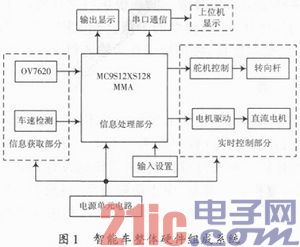
The car of the smart car competition camera group collects road information with a camera, and uses different gray values ​​of the two black boundary lines and the white track to identify the road condition, and performs real-time control on the car by processing the collected image. This paper uses the single chip MC9S12XS128 to process the collected data, and uses the steering gear and drive circuit to drive the motor to control the operation of the car.
The complete solution of the smart car design is: the road information is collected by the camera, and the LM1881 is integrated into the camera and the image field separation chip LM1881. According to the image acquired, the radius of curvature of the track is calculated. For different bending degrees of the track, different PWM signals are used to control the steering of the steering gear and the speed of the motor, so that the car can intelligently travel along the track. .
2 Design of each part of the smart car hardware circuit
2.1 Power Circuit Unit The power supply of the entire smart car comes from the rechargeable battery. Under normal circumstances, the rechargeable battery voltage is 7.2 V and the battery capacity is 2 A·h. Each module of the smart car has different requirements on the power supply, especially the voltage requirements and the voltage stability requirements, so it is necessary to select different voltage regulator chips. Different voltages are separated from the battery to power each part of the module. Figure 2 shows the smart car power supply system.
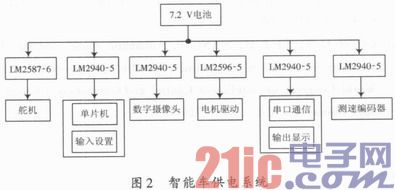
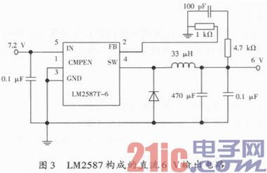
The above circuit is designed to prevent interference between the circuits, and separate power supply is provided for each module. The steering gear is special and the required power supply voltage is 6 V. The LM2587-6 voltage regulator block is used here. The specific circuit is shown in Figure 3.
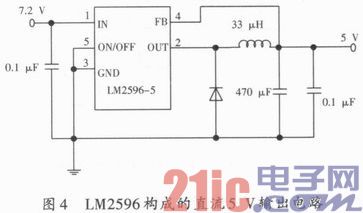
The motor drive circuit uses a LM2596 switching voltage regulator that can output a large current and can output a drive current of 3 A. The device integrates a frequency compensation and fixed frequency generator with a switching frequency of 150 kHz, which allows the use of smaller filter components compared to low frequency switching regulators. Since the device requires only four external components, a common standard inductor can be used, which optimizes the use of the LN2596 and greatly simplifies the design of the switching power supply circuit. The specific circuit is shown in Figure 4.
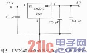
Since the digital camera has a relatively high voltage requirement, a linear regulated power supply is generally used, and the output voltage has a sharp peak without switching voltage regulation. Here, the LM2940 voltage regulator block is used. The digital camera, the speed measuring module, the serial port communication, and the single-chip microcomputer respectively use separate power supply outputs to avoid interference between them. The specific circuit is shown in Figure 5.
2.2 Real-time control part hardware design The real-time control part of the smart car mainly includes the vehicle speed and the vehicle's transformation control, that is, the steering gear control. The vehicle speed part mainly depends on the PWM in the motor drive circuit. The following is the design and the pair of motor drive circuit respectively. The steering gear control is introduced.
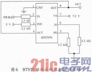
2.2.1 Motor Drive The power part of the smart car uses a small permanent magnet DC motor, which can be driven by a drive composed of separate components, or by an integrated integrated drive chip. In order to simplify the circuit board and reduce the weight of the car, the smart car adopts the integrated dedicated integrated drive chip BTS7970. The PWM pulse signal is outputted by the PWM PWM0 and PWM1 of the single-chip microcomputer, and the acceleration, deceleration and parking can be realized by two-way driving. Since one type of two-way driving circuit is designed, one of the peripheral circuits is given here, as shown in FIG.
2.2.2 Steering gear control The steering gear, also known as the servo motor, uses the servo S3010 to control the steering angle of the steering gear through the PWM signal with a period of 20 ms. The steering gear has three lines and one ground line, one power line is connected to 6 V, and the control signal line is introduced through the single-chip PWM5, and the steering angle of the servo is controlled by the duty ratio of the PWM signal output by the single chip microcomputer.
2.3 Information acquisition and input/output part The information acquisition part includes the digital image acquired by the camera and the vehicle speed information obtained by the encoder's speed measurement. Input several gear positions through the dial switch to achieve different speeds, and complete the debugging of the smart car. The specific circuit is shown in Figure 7.
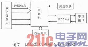
The digital camera in Figure 7 is directly connected to the MCU by using the integrated module OV7620. The 8-bit data line is directly connected to the 8-bit data port of the MCU, and the line break is respectively connected with the PT port of the MCU to complete the image acquisition. The MCU has two serial ports, and one of them communicates with the computer through MAX232 level conversion. The speed measuring module is connected to one of the single-chip PT ports to achieve speed collection. The 8-bit DIP switch is connected to the 8-bit port of the MCU, and the port is set as the input port.
3 Conclusion The smart car system has different hardware circuits depending on the individual implementation functions, and is related to the related software programs. This paper mainly introduces the hardware design circuit of the camera-based smart car, the detailed design of the power supply part of the smart car, the motor drive part, due to the limited space, only the information acquisition and input/output and MCU connection block diagram are given, indicating the connection with the single chip microcomputer. Happening.
The dimmable Class 2 led driver is the most efficient 12V/24V DC dimmable LED drivers on the market with UL/cUL 8750 Class 2 listed. The series Constant Voltage Led Driver is class 2 rated, NEMA 3R Level for outdoor use and designed to operate with any standard TRIAC (Leading edge) dimmer switch. Encased in a low profile coated metal case (with junction box) that includes 2 knock-outs, one on each side, to enable easy installation that complies with electrical code requirements.
120V Input Outdoor Rated Dimmable Led Driver
Waterproof Led Drivers, Phase-Cut Dimmable Led Drivers,Led Magnetic Transformer,Led Troffer Light Drivers,12V Led Drivers,UL Listed Outdoor Lights Drivers
Shenzhenshi Zhenhuan Electronic Co Ltd , https://www.szzhpower.com