Packaging and circuit integration to enhance the emission advantages of micro-hybrid vehicles
Key points
This article refers to the address: http://
1. Turn off the internal combustion engine when the car is not moving, which is an effective way to reduce fuel use and emissions .
2. The start/stop system can be implemented in a dual battery mode, or with a battery and boost converter, the energy stored in an inductor.
3. Issues to consider include: power consumption, transients, distortion of data and clock, and ability to reject noise.
4. There is a special battery power switch that disconnects the starter and main battery from the auxiliary power system when the engine is started.
The car's start/stop operation can shut down the engine when the car is temporarily parked, thereby reducing idle idling. This simple concept can be extended to improve fuel economy and reduce emissions. Of the approximately 80 million vehicles produced worldwide in 2011, the ICE (internal combustion engine) system remains the dominant automotive propulsion technology. However, the global trend is to try to reverse the balance to alternatives. On the one hand, the price of gasoline has remained high; on the other hand, the global mandatory government emission standards are becoming increasingly strict.
In Europe, automotive carbon dioxide emissions are a voluntary agreement between the EU and automakers, but they have been pushing for regulation because overall performance has been removed from voluntary goals. At the same time, the Euro 6 standard has been on the agenda for the next few years, and it requires a significant reduction in nitrogen oxide emissions. These advances have exacerbated the challenges faced by automakers who are trying to comply with these new standards.
Clearly, reducing fuel consumption is a key to meeting new and stringent requirements. For this reason, the HEV market will explode in the next 10 years in various models (micro hybrid, mild hybrid, full hybrid, plug-in, and full EV). To meet the 2020 goal of carbon dioxide emissions, the adoption of HEV and EV is key.
According to research firm Yole Développement, the combined demand for HEV/EV will have a compound annual growth rate of 31% over the next decade, and will grow to 50 million vehicles per year by 2020, or about half of the car production that year ( figure 1). Analysts expect micro-hybrid cars to account for the majority.
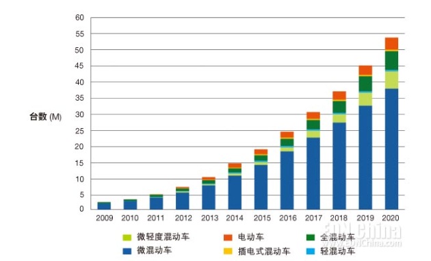
Figure 1. It is expected that the growth rate of HEV/EV demand will reach an average annual rate of 31% from now to 2020 (Yole Développement, August 2011).
Mixed type
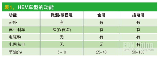
The main difference between a micro-hybrid system and a full-mix or plug-in hybrid system is that the micro-hybrid does not have an electric drive system for driving the car. The start/stop system of the micro-hybrid will reduce the engine's idle time by shutting down and restarting the ICE, such as when the car is waiting for a red light or a traffic jam. Light mixing In addition to the start/stop function, there is a regenerative braking system. The fuel economy values ​​obtained from these technologies are usually between 5% and 10% compared to the fuel consumption of conventional vehicles (Table 1).
There are now various start/stop systems. One is a super starter that uses a rugged DC starter and has a battery management system. For the end user, the super starter has an average price of $80, which accounts for about two-thirds of the start/stop system market. Automakers using this technology include BMW.
Another start/stop system is the BAS (Belt Drive AC Starter), which uses a DC-AC converter with an average power typically in the range of 1.5 kW to 3 kW. This type of system has almost no sound and provides engine restart times as low as 400ms. The end-user price of the BAS system is estimated at $300 and can be used in many mid-priced cars.
Finally, for extreme cold weather conditions that can affect the operation of a normal start/stop system, a dual battery solution or DC-DC boosting scheme can be used to maintain the voltage of the vehicle.
Double battery
In a typical dual battery technology, the power switch Q1 remains on while the ICE is running, so the load is fully powered by the main battery and an AC motor (Figure 2). When the car is parked, the ICE is turned off and the main battery becomes the main source of the load. When the engine is restarted, the main battery must provide an instantaneous current of up to 1000A for the starter motor and an instantaneous voltage drop of as low as 6V at the main battery terminals.
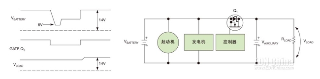
Figure 2. The dual-cell switching technique in a micro-hybrid system uses an auxiliary battery to provide a large starting current for start/stop operation. At start-up, Q1 disconnects the main battery from the power circuit and the auxiliary battery supplies the correct voltage.
In order to prevent the power supply circuit from being turned off due to transient events during battery startup, the controller will send a shutdown signal to Q1 to disconnect the main battery from the load. The auxiliary battery then powers the load to maintain the battery voltage. After the engine is successfully started and the generator is restored, Q1 is turned on and the system returns to the car driving mode.
The power switch Q1 and controller are also used as part of a reverse battery protection circuit. If the main battery is reversed, it will be turned off because there is no signal from the controller. It protects the load's circuitry by terminating the reverse current path.
Dc-dc boost
The method of using a dc-dc boost converter is similar to an auxiliary battery (Figure 3). When the engine is restarted, the bypass switch Q1 shuts off the main battery and the load, and a dc-dc converter provides the boosted voltage to the load during startup.
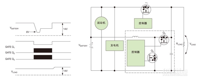
Figure 3. The dc-dc boost converter in a micro-hybrid system stores energy in the inductor's inductance. Here the function of the boost converter (in the dashed box) is equivalent to the auxiliary battery in the dual battery system.
The dc-dc boost converter includes an inductor, two power switches (Q2 and Q3), and an output capacitor. When Q2 turns on, all energy is stored in the inductor. At this point Q3 is turned off. Then, when Q2 is turned off, the inductor delivers energy to the load through Q3. The voltage on the main battery and the voltage on the load terminals determine the duty cycle of Q2. The PWM controller operates this synchronous dc-dc boost converter in continuous conduction mode to maintain the voltage across the load terminals.
Example of a micro-hybrid car
International Rectifier (IR)'s AUIRF1324S-7P surface mount MOSFETs are used as battery switches to provide maximum on-resistance down to 1mΩ and up to 240A output current. For through-hole package requirements, the company offers the AUIRF1324L in a conventional TO-262 package with a maximum on-resistance of 1.65mΩ.
The wide-lead AUIRF1324WL power MOSFET in the TO-262 package reduces the maximum on-resistance by approximately 20%. A wider lead package means that the MOSFET source terminal has more area to accommodate internal routing. The lower on-resistance and improved wire bonding in the package together increase the maximum drain current rating by approximately 30%.
All 24V 1324 series MOSFETs are suitable for battery switching applications. IR also offers 40V automotive grade MOSFETs with on-resistance as low as 1.25mΩ. These products are suitable for dc-dc converter applications.
The AUIR3240S is an automotive-grade, high-side MOSFET driver for battery power switching in start/stop applications (Figure 4). The highly integrated boost converter is specifically designed for start/stop systems and requires a grid stabilizer that disconnects the starter and main battery from the auxiliary electrical system with a power switch when the engine is started. The AUIR3240S can drive multiple MOSFETs in parallel to achieve very low on-resistance and consume less than 50μA. The device output is 15V and the input voltage range is as wide as 4V~36V. The AUIR3240S also has diagnostics for the output current and a thermal sensor interface for a robust design.
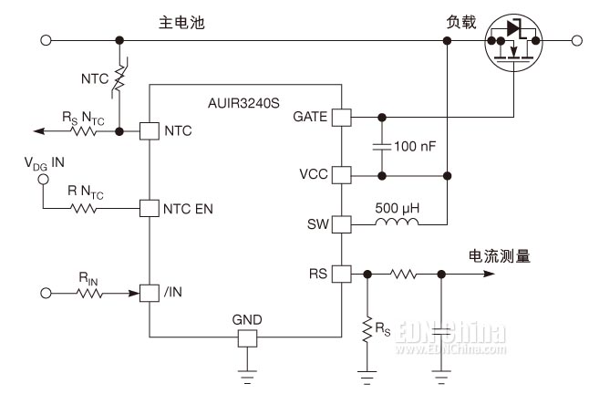
Figure 4. The dual battery system can use the grid stabilizer in the high-integration AUIR3240S power switch high-side MOSFET driver. When the engine is started, the power switch disconnects the starter and battery from the auxiliary system.
The continuous advancement of micro-mixed start/stop systems requires various solutions such as reduced starting voltage drop, integration of more electronic equipment in the starter, and further development of battery technology. Power electronics suppliers and car dealers are putting everything in place to make the necessary progress.
The Neon Led Strip is the latest and most popular LED breakthrough product, it put Led flexible light strip inside the tube,Put the strips into the led tube to make the light soft. widely used in home decoration, shopping malls showcases, shelves and other auxiliary lighting. it replaces the traditional glass neon tube With the fiber, let the city shine.
Neon LED Strip,Magic Color LED Strip,LED Flexible Tube Lights,LED Neon Rope Light
SHEN ZHEN SEL LIGHTING CO.,LTD , https://www.sellighting.com