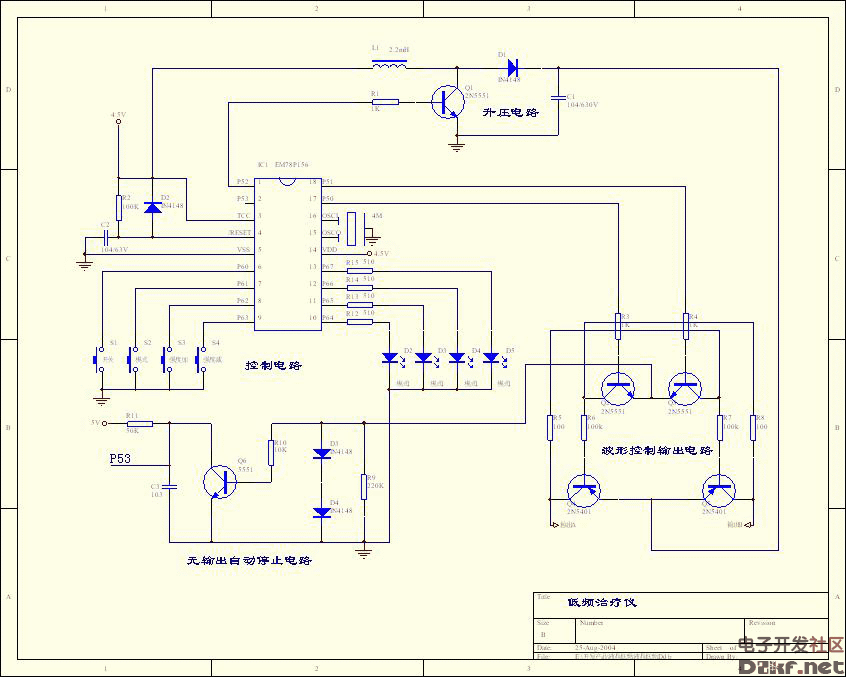
Microcomputer low frequency electrotherapy instrument circuit diagram
Low-frequency electrotherapy device circuit diagram.
Microcontroller-based low-frequency therapeutic device schematic. This system provides multiple therapeutic effects through low-frequency pulse currents, including neuromuscular stimulation, improved blood circulation, and pain relief.
Recently, many low-frequency therapy devices have been introduced into the market. The circuit design allows for various simulated massage techniques, adjustable intensity, and multiple modes. All components used are common and widely available, such as standard inductors. The output is optimized for use with dedicated patches designed for treatment purposes.
As shown in the figure, the main chip used is the EM78P156 from ELAN, and the power supply can be provided by three batteries.
Working Principle:
The EM78P156’s P5.0 and P5.1 ports control waveform changes, while P5.2 drives the boost circuit. P5.3 is used for detecting output signals and triggering automatic shutdown when no load is detected. P6.0–P6.3 are used for key detection, and P6.4–P6.7 are used for mode display.
The circuit consists of four main parts:
1. Control Circuit
This includes buttons, a microcontroller, and an indicator light. Pressing different buttons activates corresponding functions, and the LED lights up to indicate the current mode. The intensity is adjustable, and it should be set to a comfortable level, not too strong to avoid discomfort.
2. Boost Circuit
P5.2 outputs a square wave with adjustable frequency and pulse width, which controls Q1 in a switching state. This forms a boost circuit using L1, Q1, D1, and C1, allowing the capacitor C1 to charge to several times the input voltage. The boost occurs only before output, and once the signal stops, the boost circuit also stops. To increase intensity, simply extend the pulse duration—e.g., 1ms for low intensity and 2ms for higher intensity. However, the intensity change should be moderate to ensure user comfort.
3. Waveform Control and Output Circuit
When outputting, the boost circuit is activated first. Then, P5.0 and P5.1 generate identical waveforms but with a 180° phase difference. This ensures a balanced sensation on both output channels. By controlling the on/off states and adjusting the voltage, various massage techniques can be simulated. You can also apply modulation, dense waves, or other waveforms commonly used in physiotherapy to achieve effects like pain relief and weight management.
4. No Output Automatic Stop Circuit
If there is no load, no current flows through D3 and D4, so Q6 remains off, and the P5.3 port detects a high level. If this condition lasts more than 5 seconds, the device automatically shuts down. When a load is present, current flows, Q6 turns on, and P5.3 detects a low level, indicating normal operation.
This concludes the basic working principle of the low-frequency therapy device. In the next section, we will explore the program flow and how the human body responds to different waveforms. We'll also discuss which types of waveforms offer the most effective therapeutic benefits.

401-999Kva Diesel Generator,Shanghai Genset,Shanghai Power Generator,Power Generator Set
Shanghai Kosta Electric Co., Ltd. , https://www.generatorkosta.com