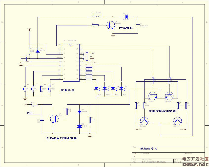
Microcomputer low frequency electrotherapy instrument circuit diagram
Microcomputer low frequency electrotherapy instrument circuit diagram
Microcomputer low frequency therapeutic instrument schematic, microcomputer low frequency therapeutic device
There are three main physiological and therapeutic effects of low-frequency pulse current: 1. Stimulating nerve and muscle tissue 2. Promoting local blood circulation 3. Pain relief. In recent years, numerous low-frequency therapeutic devices have hit the market. The circuit can output various simulated human hand massage techniques, with adjustable intensity and multiple modes available. All components are common components found on the market, and the inductance is a standard color-coded inductor. The output is preferably a patch specifically designed for treatment devices.
As shown in the diagram, the chip uses the EMC78P156 from ELAN, and the power supply can be powered by three batteries.
Working principle:
In the circuit, the P5.0 and P5.1 ports of the EM78P156 are used to control waveform changes, P5.2 drives the boost circuit, and P5.3 is the signal for receiving the output-free automatic stop circuit to automatically enter. P6.0 to P6.3 in the SLEEP state are used for key detection, while P6.4 to P6.7 are for mode display.
The circuit is divided into four parts:
First, the control circuit:
It consists of buttons, a single-chip microcontroller, and an indicator light. Pressing the corresponding button triggers the respective function output, turning on the indicator light and allowing mode adjustment. When using the indicator light across multiple modes, it serves to indicate the current mode. The intensity is adjustable, and the general output intensity should be tolerable without being too strong.
Second, the boost circuit:
At the P5.2 port, a square wave with a specific pulse width and frequency is output, causing Q1 to switch states. The power supply is formed by the boost circuit consisting of L1, Q1, D1, and C1, generating several times the voltage across capacitor C1 instead of continuously outputting signals. The boost circuit only works before the output, stopping once the voltage is boosted. To increase intensity, simply extend the output signal time; for instance, the first gear outputs a 1ms signal, while the second gear outputs a 2ms signal, making the second gear significantly stronger than the first. However, it's recommended not to vary the intensity too drastically, as slight adjustments suffice to avoid discomfort.
Third, the waveform control and output circuit:
When outputting, the booster circuit operates, boosting the voltage. Then, P5.0 and P5.1 output separately (note, these two ports cannot output simultaneously). The waveforms output by P5.0 and P5.1 are identical, with only a 180-degree phase difference. This ensures a consistent sensation on both outputs, avoiding one port having a feeling while the other does not. These two ports control the on/off of the output circuit and the voltage of the booster circuit to simulate various massage techniques. You can also refer to modulation intermediate frequencies, dense waves, sparse waves, and interdigitations, which produce therapeutic effects like pain relief and weight loss.
Fourth, the no-output automatic stop circuit:
This circuit detects when there is no load. If no current flows through D3 and D4, there is no voltage drop, Q6 lacks a base voltage, and remains off. The P53 port receives a high level, and if this persists for more than 5 seconds, it indicates no load, triggering an automatic stop. Conversely, if there is a load, current flows, D3 and D4 receive a base voltage, Q6 turns on, and the P53 port receives a low level, indicating the presence of a load.
The basic principle of the low-frequency therapy device has been outlined here. Next time, we'll delve into the program flow and how the human body perceives different waveforms. We'll also explore what types of waveforms have therapeutic effects on the human body.

Small Power Diesel Generator,Small Power Diesel Generator Set,Small Power Generator,Air Cooled Portable Diesel Generaor
Shanghai Kosta Electric Co., Ltd. , https://www.generatorkosta.com