Theoretical analysis and calculation of microscopic mechanism of terahertz wave generated by photoconductive antenna
The radiation characteristics of terahertz waves generated by photoconductive antennas are studied. The electric field strength of near-far field is calculated by Maxwell's equation and its boundary conditions. The finite difference method (FDTD) of electromagnetic time domain is used. In Matlab system software, C language is used. The program is programmed to calculate the spatial electromagnetic field distribution of the terahertz wave of the photoconductive dipole antenna and display it on a computer in pseudo-color graphics. The visualization of this electromagnetic field provides an intuitive physical basis for the design and improvement of the antenna.
The terahertz wave refers to electromagnetic radiation having a wavelength ranging from 3 μm to 3 mm (011 to 10 THz), and the wavelength band is between the microwave and the infrared light. With the development of ultra-fast laser technology and low-scale semiconductor technology, the technology of THz electromagnetic wave generation, the research of THz radiation mechanism, THz detection technology and application technology have been rapidly developed. At present, there are mainly two methods for generating pulsed THz radiation: a photoconductive antenna generates THz electromagnetic waves and optical rectification produces THz. The former uses a femtosecond laser pulse to trigger a photoconductor under DC bias, and a dipole antenna is generated by a coherent current to generate terahertz radiation; optical rectification is a nonlinear effect, using femtosecond laser pulses and a nonlinear medium (LiNbO3, The interaction of LiTaO3, ZnTe, etc. to produce a low frequency polarization field can also radiate THz electromagnetic waves. In recent years, there have been many reports on the generation of THz electromagnetic waves by photoconductive antennas at home and abroad. Darrow et al. explained the theory of terahertz waves generated by photoconductive antennas in detail, and compared the terahertz radiation generated by gallium arsenide (GaAs) and indium phosphide (InP) as matrix materials for photoconductive antennas. Hattori et al. studied the time characteristics of terahertz waves generated by large-aperture photoconductive antennas, considering the effects of semiconductor carrier lifetime and relaxation time on terahertz radiation. The large-aperture photoconductive antenna will produce saturation under the illumination of strong laser pulses. Darrow and so on have theoretical simulations respectively. It is concluded that the shielding effect of the radiated electric field on the semiconductor surface on the bias electric field is the main cause of saturation. Shi Wei et al. studied the radiation characteristics of terahertz waves generated by semi-insulating gallium arsenide (GaAs) antennas.
Based on the research at home and abroad, the theoretical analysis and calculation of the microscopic mechanism of the terahertz wave generated by the photoconductive antenna are carried out. The surface current of the photoconductor and the radiated electric field of the near-far field are calculated by Maxwell's equation and its boundary conditions. It is seen that the terahertz wave radiation intensity is proportional to the surface current under near-field conditions. The terahertz wave radiation intensity under far-field conditions is proportional to the width, power and bias field strength of the trigger light pulse. For the theoretical analysis results, the radiation characteristics of the photoconductive antenna are calculated by the finite difference time domain method (FDTD).
1 Photoconductive dipole antenna structure and theoretical analysis
1.1 Photoconductive dipole antenna structure
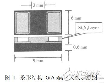
Semi-insulating GaAs material has excellent optoelectronic properties, is the production of optoelectronic materials, Xiao Jian, etc.: Femtosecond laser triggers photoconductive antenna to produce terahertz wave. Photoconductive antenna is ideal. The base material GaAs material can have a resistivity of 10^. 7~10^8, the breakdown strength is 250kV/cm; the chip material of the photoconductive dipole antenna made of semi-insulating GaAs material is taken as an example. The structure and size parameters of the photoconductive antenna are introduced, and an intuitive schematic diagram is given. The semi-insulating GaAs material has a dark state resistivity Ï=5&TImes; 107 Ωcm, a carrier concentration of n≈1014 cm-3, a carrier mobility of μ>5500 cm 2 /(Vs), a chip thickness of 016 mm, and an outer dimension of 610mm&TImes; 910mm; an Au/Ge/Ni alloy electrode (strip antenna) with a thickness of 900 nm was deposited by electron beam evaporation, and annealed to form an ohmic contact with the GaAs chip material. The electrode size was 6 mm & TImes; 3 mm, radius of the fillet It is 111mm, the gap between the two electrodes is 3mm; the insulating protective layer is made of Si3N4 thin film material, and its structure is shown in Fig. 1.
1.2 theoretical analysis
The theoretical analysis of the terahertz wave generated by the GaAs photoconductive antenna uses the "current source instantaneous impulse model". The model analysis believes that the THz wave radiated by the photoconductor is generated by the transient current excitation of the photoconductor surface. According to the Maxwell equation, the surface current Js(t) is expressed as
Js(t)=σs(t)(Eb+Es(t)) (1)
Where σt is the time domain surface conductance; Eb is the bias electric field, and Es(t) is the radiation electric field of the photoconductor surface. The relationship between Js(t) and Es(t) can be obtained from the boundary conditions of the Maxwell equation.
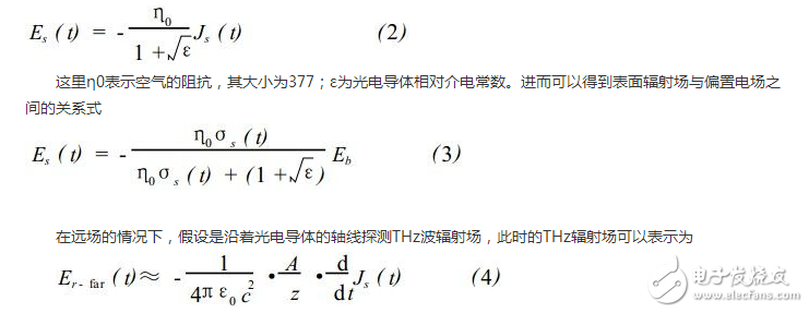
Where A is the illumination area of ​​the photoconductor electrode gap; z represents the distance from the radiation center to the observation point.
According to the above theoretical analysis, the radiation intensity of THz wave is proportional to the surface transient current under near-field conditions; the intensity of THz electromagnetic wave is determined by the intensity of the trigger light pulse under far-field conditions. In addition, the dipole chip of the photoconductor is an electrode that generates THz, and at the same time has the function of a transmitting antenna, and the radiation efficiency of the antenna can be improved by designing the shape and structure of different metal antennas.
2 electromagnetic wave time domain finite difference method (FDTD)
2.1FDTD equation
The main idea of ​​the finite-difference time-domain method is to discretize the Maxwell equation in space and time, replace the continuous derivative with the form of the central difference quotient, replace the first-order differential equation with the difference equation, and gradually advance the solution on the time axis. Give an equation
Where ε0 represents the dielectric constant in vacuum; μ0 represents the magnetic permeability in vacuum.
For a similar form of magnetic field, only the coefficient part will be different. The FDTD equation of the magnetic field can be obtained by changing the conductivity in the electric field formula to magnetic permeability and dielectric constant to magnetic permeability.
2.2 Absorption boundary conditions
Commonly used absorbing boundary conditions include Mur absorbing boundary conditions and perfectly matched layer (PML) absorbing boundary conditions. Mur absorbing boundary conditions are suitable for poor computer performance and low calculation accuracy. PML absorbing boundary conditions have higher requirements on computers. The calculation accuracy is high. PML absorption boundary conditions are used in this paper.
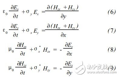
The PML absorption boundary condition is composed of a special anisotropic material. The perfectly matched layer is a lossy medium. The transmitted wave entering the PML layer will decay rapidly, and it has a good absorption effect on the incident wave. A layer of virtual lossy media is constructed outside the FDTD boundary such that the incident waves in all directions reflect little or even zero on the boundary. In 1994, Beernger constructed a non-physical absorption medium based on this idea, which is connected to the outer boundary of the FDTD grid, and its wave impedance has nothing to do with the incident angle and frequency of the outwardly scattered wave. Taking the two-dimensional TE case as an example, in the PML medium, the Beerng splits the Hz into two components Hzx and Hzy, and Hz=Hzx+Hzy, in order to introduce a new degree of freedom of the specified loss. Then rewrite the Maxwell equation to
σ and σ* represent the conductivity and permeability in free space, respectively. At that time σx = σy = σ3x = σ3y, equation (6) degenerates into the Maxwell equation in free space, so it can be considered that the above equation describes a general case, and free space is one of the special cases.
2.3 Using Matlab program to calculate the radiation characteristics of photoconductive antenna
(1) Selection of parameters in programming. In order to ensure the stability and convergence of the solution, the length of the discrete mesh is Δx=Δy=Δz=δ=λ/12; the time step is Δt=δ/2c, where c is the speed of light in free space, at 011 THz For example, the electromagnetic wave is 115 cm in the x direction, and the values ​​of y and z are the same as x;
(2) Set the excitation source. In the calculation, the Gaussian pulse excitation source in differential form is used to simulate Ei(t)=[(t-t0)/Ï„]exp-[4Ï€(t-t0)2]/Ï„2, where Ï„ is a constant, which determines The width of the Gaussian pulse;
(3) Write a Matlab program for calculation. Calculate the calculation program in C language, calculate in Matlab710 software, the hardware configuration is Core Core single core 116GHz, memory 1GB, running time is about 2 minutes and 20 seconds, the calculation result is shown in Figure 2.
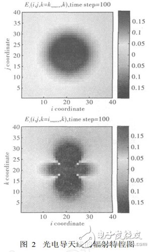
The radiation characteristic diagram of the photoconductive antenna antenna calculated by Matlab is shown in Fig. 2. The electromagnetic field distribution of the antenna complex radiation can be seen from the graph, which can deepen the understanding of the working principle of the antenna, and provides a further improvement of the antenna structure. Based on the physical basis, the power and efficiency of the terahertz wave radiated by the photoconductive antenna are improved.
3 Conclusion
Through the theoretical analysis and calculation of the photoconductive antenna, the FDTD method is used to analyze the radiation characteristics of the antenna. By modeling and simulating the Matlab program for specific calculation, the radiation pattern of the antenna can be visually seen. It can be seen from the above results analysis that the FDTD method is a practical and feasible method in the numerical calculation of electromagnetic fields. Using Matlab for simulation operations, the iteration of the field and the absorption in the boundary region can be understood more accurately. When applying the FDTD method, it is necessary to pay attention to the fact that in the process of programming, the division of the grid plays an important role and must be handled with care. Another important factor is the simulation of the excitation source, the selection of the appropriate excitation source form and the appropriate The method adds the excitation source to the FDTD iterative calculation.
Shenzhen Xcool Vapor Technology Co.,Ltd , https://www.szxcoolvape.com