Share 15 op amp basics
1. There is a balance resistor in the general inverting/in-phase amplifier circuit. What is the role of this balance resistor?
(1) Provide a suitable static bias for the transistors inside the chip. The internal circuitry of the chip is usually directly coupled, it can automatically adjust the static operating point, but if an input pin is directly connected to the power supply or ground, its automatic adjustment function is not normal, because the chip inside the chip The voltage of the ground wire cannot be raised, and the voltage of the power supply cannot be pulled down. This causes the chip to fail to meet the conditions of virtual short and virtual disconnection, and the circuit needs additional analysis.
(2) Eliminate the influence of the static base current on the output voltage, and the size should be balanced with the equivalent resistance value of the external DC path of the two input terminals, which is why it is named.
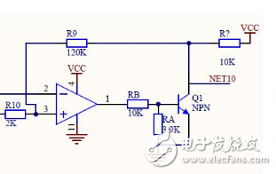
2. What is the role of a capacitor on the feedback resistor compared to the comparator?
(1) The feedback resistor and the capacitor form a high-pass filter, and the local high-frequency amplification is particularly powerful.
(2) Prevent self-excitation.
3. What are the consequences of the op amp non-inverting amplifier circuit if it is not connected?
(1) Burning the operational amplifier may damage the operational amplifier, and the resistor can function as a partial voltage.
4. Pull up the capacitor at the input of the op amp. What role does the pull-down resistor play?
(1) is to get the problem of positive feedback and negative feedback, depending on the specific connection. For example, if I input the voltage signal and output the voltage signal, and then take a line at the output end and connect it to the input section, then due to the above resistor, part of the output signal passes through the resistor to obtain a voltage value, and the input voltage is shunted. This makes the input voltage smaller, which is a negative feedback. Because the signal output from the signal source is always constant, the output signal can be corrected by negative feedback.
5. What is the function of the resistor RF connected to the integrator at the two ends of the integrating capacitor?
(1) A bleeder resistor to prevent the output voltage from running out of control.
6. Why are resistors and capacitors connected in series at the input of the op amp?
(1) If you are familiar with the internal circuit of an operational amplifier, you will know that no matter what operational amplifier is composed of several transistors or MOS transistors. In the absence of an external component, the op amp is a comparator. When the voltage at the same phase is high, it will output a level close to the positive voltage, and vice versa... but the op amp does not seem to be of much use, only In the case of an external circuit, the feedback form is formed, so that the op amp has functions such as amplification, flipping, etc...
7. Operational amplifiers with the same phase amplification circuit If the balance resistance is wrong, what are the consequences?
(1) The same phase is unbalanced. When the input is 0, there will be an output. When the input signal is output, the output value is always larger (or smaller) than the theoretical output value by a fixed number. (2) The error caused by the input bias current cannot be eliminated.
8. What is the amplification factor of the ideal integrated operational amplifier? What is the voltage between the non-inverting input and the inverting input? (1) The amplification is infinite, the input impedance is infinitesimally small, the same direction is input and reversed. The voltage between the inputs is almost the same (not 0 oh!!! For example, the same end is 10V, the reverse end is 9.99999V), just finished the electrician, remember!
9. Why is the open loop gain of an ideal op amp infinite?
(1) The actual open-loop gain of the op amp reaches 100,000 or more, which is very large. Therefore, the open-loop gain of the actual operational amplifier is considered to be infinite, and the virtual ground is derived therefrom.
(2) Deriving virtual ground is only for inverting amplifiers. I saw in the book that the open-loop gain of the op amp is infinite, which allows us to design the circuit, the closed-loop gain can be independent of the open-loop gain, and only depends on the external components. It is to sacrifice the large open loop gain in exchange for the stability of the closed loop gain.
(3) Deriving virtual ground is not only an inverting amplifier for the negative feedback connection; there is no virtual ground for positive feedback.
(4) It is well understood that the assumed gain is small. For an output voltage, the difference between the voltages applied across the op amp is relatively large. If connected to a negative feedback state, the voltage across the op amp will be inconsistent. , causing an error in amplification.
(5) The implementation of the “virtual short†of the op amp has two conditions: 1) the open loop gain A of the op amp is large enough; 2) there must be a negative feedback circuit. First, let's talk about the first point. We know that the output voltage Vo of the op amp is equal to the difference between the voltage of the non-inverting input terminal and the voltage of the inverting input terminal, Vid, multiplied by the open-loop gain A of the op amp. That is, Vo = Vid * A = (VI + - VI-) * A ( 1 ) Since the output voltage of the op amp does not exceed the supply voltage in practice, it is a finite value. In this case, if A is large, (VI+ - VI-) is necessarily small; if (VI+ - VI-) is small enough, then we can actually treat it as 0, this time there will be VI+ = VI-, that is, the voltage at the non-inverting input of the op amp is equal to the voltage at the inverting input. It seems to be connected together. This is called “virtual short circuitâ€. Note that they are not really connected together, and there is resistance between them, which must be kept in mind. In the above discussion, how do we get the result of "virtual short"? Our starting point is formula (1), which is the characteristic of the op amp, there is no problem, we can rest assured. Then, we made two important assumptions. One is that the output voltage of the op amp is limited. This is no problem. The output of the op amp will certainly not exceed the power supply. Therefore, this assumption is absolutely true, so we will not mention it later. The second is that the open loop gain A of the op amp is large. The A of a normal op amp usually reaches 10, 7 or 7 or even higher. This assumption is generally no problem, but don't forget that the actual open loop gain of the op amp is related to its working state. If you leave the linear area, A will not. It must be big, so this second hypothesis is conditional, and we will remember this first. Therefore, we know that when the open loop gain A of the op amp is large, the op amp can have a "virtual short". But this is only a possibility, not automatic, and just take an op amp and say that its two inputs are "virtual short". No one will believe it. “Virtual Short†can be implemented in a specific circuit. The conditions for “virtual short†are: 1) the open loop gain A of the op amp is large enough; 2) there must be a negative feedback circuit. After understanding the conditions of "virtual shortness", it is easy to judge when and when we can't use "virtual short" for circuit analysis. In reality, condition (1) is true for most op amps, and the key is to look at the work area. If it is the circuit on the book, it is judged by calculation; if it is the actual circuit, it is known whether the output voltage of the instrumentation op amp is reasonable. There is also a situation related to "virtual short" called "virtual ground", that is, there is a "virtual short" when the input is grounded, not a new situation. Some books say that you can use "virtual short" under deep negative feedback. I think this is not accurate. I think the underlying thinking is that the op amp is more likely to work in the linear region with deep negative feedback. But this is not absolute. When the input signal is too large, the op amp with deep negative feedback will still be saturated. Therefore, it should be judged to be the most reliable with the output voltage value.
10. Add the input signal directly to the non-inverting input. The inverting input is grounded through the resistor. Why is U_ = U+ = Ui≠0? Is it not a virtual ground?
Question added: To form a virtual short to meet certain conditions. That constitutes a virtual place to meet certain conditions? What is it? Why?
(1) In the in-phase amplifying circuit, the output passes the feedback, so that U(+) automatically tracks U(-), so that U(+)-U(-) will be close to zero. It seems that the two ends are short-circuited, so it is called "virtual short".
(2) Due to the virtual short phenomenon and the high input impedance of the op amp, the current flowing through the two input terminals of the op amp is very small, close to 0. This phenomenon is called “virtual break†(virtual break is derived from virtual short, not It is considered that the two are contradictory. (3) The virtual ground is in the reverse-phase operational amplifier circuit, the (+) terminal is grounded, and the (-) is connected to the input and feedback network. Due to the existence of the virtual short, U(-) and U(+)[potential equal to 0] are very close, so the (-) end is false grounded - "virtual ground" (4). Condition: virtual short is the closed loop of the in-phase amplifier circuit (Simply speaking, there is feedback) An important feature of the working state, the virtual ground is an important feature of the inverting amplifier circuit in the closed-loop operating state. Pay attention to understanding the conditions of the virtual short (such as "close to equality"), it should be ok.
11. I always think that the model of the operational amplifier is a bit awkward. The first is “virtual shortâ€. Because “virtual shortâ€, when the operational amplifier is connected to the non-inverting amplifier, the potentials of the two inputs are the same. If the waveform of the input is measured, The same is true, this is like a common mode signal. In fact, there are still small differential mode signals on the two input terminals, but the general instrument can't measure them. However, in this way, because of the "virtual short", it is artificial (because of the virtual Short is the result of deep negative feedback, which artificially increases the common-mode signal at both inputs, which poses a challenge to the performance of the op amp. Why is an op amp used like this?
(1) The common mode signal of the non-inverting amplifier is much larger than the inverting amplifier, and the common mode rejection ratio is required to be high.
(2) My view on "common mode signal rejection of both amplifiers and inverting amplifiers" The advantage of the op amp common-mode signal rejection ratio (db value) depends mainly on the internal (only internal) differential amplifier of the op amp. The degree of symmetry and gain. It is obvious that without any op amp providing its common mode rejection ratio, the structural conditions of the external circuit are added. For single-ended inputs, the equivalent common-mode value is half the input value, whether in-phase or inverting. However, since the input impedance of the in-phase amplification is usually larger than the inverting amplification, the anti-interference ability is of course worse. As described above, when the inverting input is performed, the voltage at the inverting terminal is almost zero, so the differential pair tube collector voltage has only one tube change. When the input is in phase, the voltage of the inverting terminal is equal to the voltage of the non-inverting terminal, so the common mode voltage and the input voltage are equivalent! That is to say, the differential pair tube collector voltage has a direction in addition to the two tubes that change in different directions at the same time. The amount of change in the same direction, this is the common mode output voltage. It is added in phase with the voltage of one of the tubes. Therefore, it is easy to cause the tube to become saturated (or cut off). Fortunately, the amplification of the common mode voltage is only tens of thousands of parts of the differential mode amplification. The above does not mean that the common mode rejection suppression ratio of the differential mode input and the common mode input of the amplifier is different! It should be that the non-inverting input adds a common mode signal equivalent to the input amount! Therefore, when the input signal is large, Use the in-phase amplification mode with caution.
12 Why does the op amp generally have to be scaled up? The significant difference between the inverting input method and the non-inverting input method is that the inverting input method has no current at this resistor because it has a balanced resistor connected to ground at the same phase (because of the operation The input resistance of the amplifier is extremely large, so this non-inverting terminal is approximately equal to the ground potential, which is called "virtual ground", and the inverting terminal is very close to the potential of the non-inverting terminal. Therefore, there is also a "virtual ground" at the inverting end. . The advantage of having a virtual ground is that there is no common mode input signal, even if the common mode rejection ratio of this op amp is not high, there is no common mode output. In the same phase input connection, there is no "virtual ground". When a single-ended input signal is used, a common-mode input signal is generated. Even if an operational amplifier with a high common-mode rejection ratio is used, there is still a common-mode output. Therefore, when using it, it is best to use the inverting input method.
13. Some op amps will have an output even if no voltage is input after power-on, and the output is not small, so VCC/2 is often used as the reference voltage.
(1) The output is output without any input, which is caused by the asymmetry of the design structure of the op amp itself, which is the input offset voltage Vos that we often say, which is a very important performance of the op amp. parameter. The op amp commonly used VCC/2 as the reference voltage is because the op amp is in a single-supply operation state. At this time, the real reference of the op amp is VCC/2, so a DC offset of VCC/2 is often provided at the positive terminal of the op amp. In the case of positive and negative dual power supply, it is often referenced to the ground. The choice of op amps requires attention to many things. Under less stringent conditions, it is often necessary to consider the operating voltage, output current, power consumption, gain bandwidth product, and price of the op amp. Of course, when used under special conditions, different impact factors need to be considered.
14. Why is the amplifier circuit composed of operational amplifiers generally sampling the inverting input mode? (1) The significant difference between the inverting input method and the non-inverting input method is: the inverting input method, because a balanced resistor is connected to the ground at the same phase. There is no current on this resistor (because the input resistance of the op amp is extremely large), so this non-inverting terminal is approximately equal to the ground potential, called "virtual ground", and the inverting terminal is very close to the potential at the non-inverting terminal. Therefore, there is also a "virtual ground" at the inverting end. The advantage of having a virtual ground is that there is no common mode input signal, even if the common mode rejection ratio of this op amp is not high, there is no common mode output. In the same phase input connection, there is no "virtual ground". When a single-ended input signal is used, a common-mode input signal is generated. Even if an operational amplifier with a high common-mode rejection ratio is used, there is still a common-mode output. Therefore, when using it, it is best to use the inverting input method.
(2) The positive phase is the oscillator, the inverting can stabilize the amplifier, and the negative feedback is connected. (3) From the principle, it is possible to connect to the same analog circuit. However, the signal that is amplified during the actual application (that is, the differential mode signal) tends to be small, so it is necessary to pay attention to suppressing noise (usually expressed as a common mode signal). In the same way, the amplification circuit has a poor ability to suppress the common mode signal, and the signal that needs to be amplified is submerged in the noise, which is not conducive to post processing. Therefore, an inverting proportional amplification circuit with better suppression capability is generally selected.
15. What are the important features of the op amp?
(1) If the voltage on both inputs of the op amp is 0V, the output voltage should also be equal to 0V. But in fact, there is always some voltage at the output, which is called the offset voltage VOS. If the offset voltage at the output is divided by the noise gain of the circuit, the result is called the input offset voltage or the input reference offset voltage. This feature is usually given in VOS in the datasheet. The VOS is equivalent to a voltage source in series with the inverting input of the op amp. A differential voltage must be applied to both inputs of the amplifier to produce a 0V output.
(2) The input impedance of an ideal op amp is infinite, so no current flows into the input. However, a real op amp using a bipolar junction transistor (BJT) in the input stage requires some operating current, which is called bias current (IB). There are usually two bias currents: IB+ and IB-, which flow into the two inputs, respectively. The range of IB values ​​is large. The bias current of a particular type of op amp is as low as 60fA (large z passes every 3μs through one electron), while some high-speed op amps can have bias currents of up to tens of mA.
(3) The power supply voltage range required for the first single-chip op amp to operate normally is ±15V. Today, op amps are moving toward low voltages due to increased circuit speeds and power supplies from low-power sources such as batteries. Although the op amp's voltage specifications are usually specified as symmetrical two-pole voltages (eg ±15 V), these voltages do not necessarily require a symmetrical voltage or a two-pole voltage. For op amps, a ±15V supply is equivalent to a +30V/0V supply, or a +20V/–10V supply, as long as the input is biased within the active region (ie, within the common-mode voltage range). The op amp does not have a ground pin unless the negative voltage rail is grounded in a single-supply application. No device in the op amp circuit needs to be grounded. The input voltage swing of high speed circuits is smaller than that of low speed devices. The higher the speed of the device, the smaller its geometry, which means the lower the breakdown voltage. Due to the low breakdown voltage, the device must operate at a lower supply voltage. Today, op amps typically have a breakdown voltage of around ±7V, so high-speed op amps typically have a supply voltage of ±5V, and they can operate at a single supply voltage of +5V. For general purpose op amps, the supply voltage can be as low as +1.8V. This type of op amp is powered by a single power supply, but this does not necessarily mean that a low supply voltage must be used. The terms single supply voltage and low voltage are two related and independent concepts.
16. What is the amplification principle of an op amp? The op amp core is a differential amplifier. That is, the two triodes are connected back to back. Co-share the current of a cross current source. One of the transistors is the positive input of the op amp and the other is the reverse input. The positive input transistor is amplified and sent to a power amplifier circuit to amplify the output. Thus, if the voltage at the forward input rises, the output naturally becomes larger. If the voltage at the inverting input rises, the inverting tertiary tube and the forward three-stage tube share a constant current source. The reverse three-stage current is large, and the forward direction is small, so the output will be reduced. So called reverse input. Of course, there are many other features inside the circuit, but the core is like this.
Etching cutting die is mainly used in the die-cutting industry to cut product labels. Generally applied to trademarks, printing and packaging, various paper art, fabric creation, home beautification, office decoration, double-sided adhesive, single-sided adhesive, stickers and more.
The main characteristics of the die cuts are that it has no jointing, high precision and a higher service life than laser cutting dies. The size of the product is stable during the die-cutting process, the maintenance requirements are simple during the storage of the moulds, and long-term storage will not affect the size of the product.
We customize diverse patterns Mould products with drawings provided by customers. We are equipped with professional metal etching equipment and exposure development equipment. The accuracy of our moulds can be maintained at ±0.05mm, the material uses is high hardness 65 Mn Steel. We can guarantee that our hard mould cutting die have straight blade lines, consistent width and height, as well as the blade height and bottom thickness accuracy also meet the customer's requirements.
Hard Mould Cutting Die,Diverse Patterns Mould, High Hardness 65 Mn Steel,Die cuts
SHAOXING HUALI ELECTRONICS CO., LTD. , https://www.cnsxhuali.com