4 typical optocoupler feedback connections
Optocoupler (optionally known as OC) is also known as opto-isolator or optocoupler, referred to as optocoupler. It is a device that transmits electrical signals by means of light. Generally, an illuminator (infrared light emitting diode (LED)) and a light receiver (photosensitive semiconductor tube) are packaged in the same package. When the input terminal energizes the signal, the illuminator emits light, and after receiving the light, the photocurrent is generated and flows out from the output end, thereby realizing the "electricity-light-electricity" conversion. The optocoupler that couples the input signal to the output end with light as a medium, because of its small size, long life, no contact, strong anti-interference ability, insulation between output and input, one-way transmission of signals, etc. Widely used on circuits.
In some laboratories or high-demand occasions, for the safety of the experimenter, the input power of the experiment is generally isolated from the mains by a 1:1 power frequency transformer, so that the laboratory experimenter does not touch any of the lines. There is no danger of electric shock on the root line because the isolated power supply is not connected to the earth. In industrial control equipment, power ground isolation between two systems is sometimes required, such as isolated ground noise, isolation of high common-mode voltage, etc., using a DC converter with a transformer to separate the two power supplies, so that They are independent of each other.
In general isolated power supplies, optocoupler isolation feedback is a simple, low-cost way. However, for the various connection methods of optocoupler feedback and their differences, no in-depth research has been seen yet. Moreover, in many occasions, because the understanding of the working principle of the optocoupler is not deep enough, the optocoupler connection method is confusing, which often causes the circuit to fail to work normally. This study will analyze the working principle of optocoupler in detail, and compare several typical methods of optocoupler feedback.
1 Common connection methods and working principle
The optocoupler has small volume, long service life, wide operating temperature range and strong anti-interference performance. It has no contact and the input and output are completely electrically isolated, so it is widely used in various electronic devices. Optocouplers can be used in circuits such as isolation circuits, load interfaces, and various household appliances.
The optocoupler models commonly used for feedback are TLP521, PC817, etc. Here, the TLP521 is taken as an example to introduce the characteristics of such an optocoupler.
The primary side of the TLP521 is equivalent to a light-emitting diode. The larger the primary current If, the stronger the light intensity, and the larger the current Ic of the secondary transistor. The ratio of the secondary triode current Ic to the primary diode current If is called the current amplification factor of the optocoupler, which varies with temperature and is greatly affected by temperature.
Feedback is usually selected in conjunction with TLP521. At this time, the working principle of the TL431 is equivalent to a voltage error amplifier with an internal reference of 2.5 V, so between the 1 pin and the 3 pin, the compensation network is connected.
The common optocoupler feedback is the first connection, as shown in Figure 1. Note that the ground on the left is the output voltage ground, and the ground on the right is the power supply voltage of the chip. The two are isolated by optocouplers.
The working principle of the connection shown in Figure 1 is as follows: When the output voltage rises, the voltage of the 1 pin of the TL431 (corresponding to the inverting input terminal of the voltage error amplifier) ​​rises, the voltage of the 3 pin drops, and the primary current of the photocoupler TLP521 If Increase, the other end of the optocoupler output current Ic increases, the voltage drop across the resistor R4 increases, the com pin voltage drops, the duty cycle decreases, the output voltage decreases; conversely, when the output voltage decreases, the adjustment process similar.
A common second connection is shown in Figure 2. Different from the first connection method, the fourth pin of the optocoupler in the connection is directly connected to the error amplifier output end of the chip, and the voltage error amplifier inside the chip must be connected to the non-inverting terminal potential higher than the inverting terminal potential. Form, using a feature of the op amp --- When the op amp output current is too large (beyond the op amp current output capability), the op amp's output voltage value will decrease, the larger the output current, the more the output voltage drops.
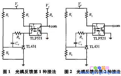
The working principle of the connection method shown in Figure 2 is: when the output voltage rises, the primary current If increases, and the output current Ic increases. Since Ic has exceeded the current output capability of the voltage error amplifier, the com pin voltage drops. The air ratio is reduced and the output voltage is decreased; conversely, when the output voltage is decreased, the adjustment process is similar.
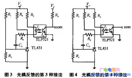
A common third connection is shown in Figure 3. Similar to Figure 1, the difference is that there is a resistor R6 in Figure 3. The resistor is used to inject an additional current into the TL431 to prevent the TL431 from working properly due to too small injection current.
A common fourth connection is shown in Figure 4. The connection method is similar to the second connection method. The difference is that a resistor R4 is connected between the com terminal and the photocoupler pin 4, and its function is consistent with R6 in the third connection method, and the working principle is basically the same. 2.
This website tries to open micro- and small-enterprise business advertising business; maintenance point recommended items. The fee is affordable and effective! Welcome to contact in QQ or email!
Why do you want to do online advertising contact?
|
- 0
- like
| Try to find the information you want to see. Inverter sensor patch three no weight loss camera LCD monitor does not boot digital camera XC9237 projector switching power supply laptop processor IPSUSB skills entrepreneurial black screen water heater can not boot circuit design silent transformer XC6102 without sound XC6112 display regulator no image microwave player successful silent GPS tea no picture XC6222 health XC6372 relay filter ML6209 switch washing machine digital camera description remote control without grating 555 protection circuit cancer self-closing Linux charger mobile phone shutdown noise inverter oscilloscope robot Windows antenna indicator light is not bright fiber life transformer stomach market alarm Hard disk watch embedded system woman maintenance process memory XC9236 converter router interview server kidney RFIDLED driver Konka CDMA instrument Panasonic CCD flashing engine multimeter Apple liver motor resistance keyboard integrated circuit current transformer triode governor power supply LED |

2D Wireless Scanner Product Features: 1. Excellent performance, can collect barcodes under almost any conditions 2. Satisfy the 24-hour uninterrupted scanning power, independent power display 3. Exclusive Wi-Fi friendly mode eliminates Bluetooth interference
ShengXiaoBang is the Barcode scanner and Printer manufacturer in China.
with over 6years export experience that we know the quality is our soul.
Many clients re-order to us for our stable quality and competitive price.
please contact us for more information and you will get what you really want.
2D Wireless Scanner ,Wireless 2D Barcode Reader,Cordless 2D Barcode Scanner,Scanner 2D Wireless
ShengXiaoBang(GZ) Material Union Technology Co.Ltd , https://www.sxbgz.com