Principle of VIPer22A and its application in switching power supply
The VIPer22A is a power chip that works in switch mode. It has the following characteristics:
The operating frequency is fixed at 60 kHz.
The chip itself uses a 9v-38v supply voltage. The power supply range is wide and it is easy to match the switching transformer.
The voltage regulation mode uses a current control mode.
The chip has built-in perfect overvoltage, overcurrent and overtemperature protection circuits.
Directly draw a high-voltage current source from the internal switch of the chip to provide a switch circuit to start using.
The switching power supply consisting of VIPer22A can provide up to 20w of output power, which can be used for portable battery charging circuits and standby power supplies for TVs, monitors and other electrical equipment. It can also be used independently as a power supply for small appliances with comparable power consumption, such as game consoles, satellite receiving equipment, audio, and so on.
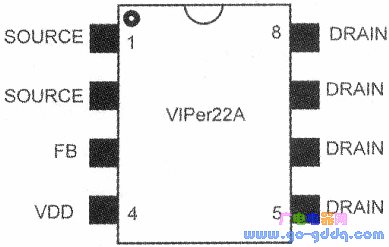
The pin arrangement of the VIPer22A chip is shown in the figure above.
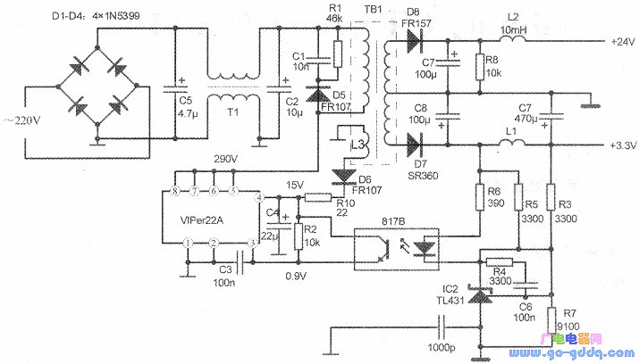
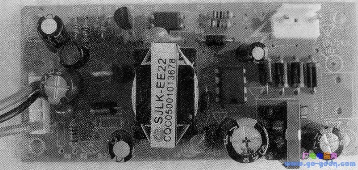
The above figure and the following figure are the power supply practical circuit and physical picture composed of VIPer22A. This is a universal power supply. It has three output voltages of 5V, 24V and 3.3V. It is also suitable for power supply of VCD, DVD and other electrical appliances. It can also be used for maintenance power supply era.
Regulator circuit
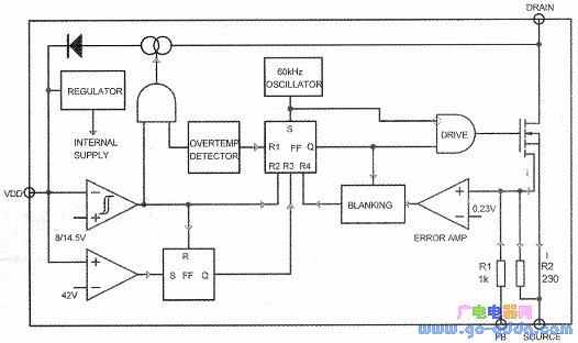
As shown in the figure above, the VIPer22A integrates a high-voltage field-effect switch tube with a breakdown voltage of 700V.
The VIPer22A's unique voltage regulation mode is quite different from conventional power chips.
The VIPer22A maintains the output voltage stability by controlling the current of the switch. At the moment of power-on, VIPer22A starts to start, the internal oscillation circuit starts, and the output pulse voltage drives the switch to conduct. The current in the switching transformer rises rapidly, and the conduction current will enter the ground through the source of the switching tube to form a loop. Sampling of the switch current is accomplished by resistor R2. When the current of the switch tube reaches the design limit quickly, the sampling current will generate a voltage drop of more than 0.23v on the R2. The internal error amplifier of the chip outputs a high voltage, and the drive circuit is turned off, so that the switch tube is cut off and the load current is reduced. After the secondary voltage of the switching transformer is established, the external FB terminal of VIPer22A will get a feedback current proportional to the secondary voltage, which is superimposed with the sampling current to form an error voltage on the resistor R2. The error voltage controls the comparison amplifier. , the output voltage can be stabilized. As shown in the figure, in the voltage regulation section of VIPer22A, the source current of the switching transistor is not directly used as the sampling current, but another small current i is taken from the switching tube, thereby indirectly sampling I. There is a fixed ratio of 560 between the currents, that is, the switching tube current I is 560 times that of the small current i. Since the sampling current is greatly reduced, a larger 230 ohm resistor can be used as the sampling resistor, and the output voltage is more stable and accurate while reducing the loss. The reference voltage for error comparison is 0.23V.
It can be seen that the maximum current of the VIPer22A is completely determined by the internal circuit. When the FB terminal is grounded, the switch tube current l reaches the design limit, that is, the maximum value. Because the input impedance of the op amp is extremely high, the sampling current i can be seen as directly entering the ground through a parallel circuit of resistor R1 (feedback resistor) and R2 (sampling resistor). In this way, we can calculate the maximum value of the switching tube design current by calculation:
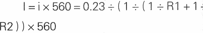
Substituting the resistance value, we calculate |=0.6888A, which is the design limit of the switching tube current. In the switching power supply, the switching tube current plays a decisive role in the output power, and the current is determined. The maximum output power of the switching power supply of the VIPer22A group is basically determined.
Stator and rotor laminations are an important part of motors and generators. For medium-sized laminations with a great quantity, we usually use compound puncing. The advantages of compound punching is the process is suitable for mass production of medium-sized stator and rotor laminations. And the lead time is shorter. Usually the outer diameter is from 300mm-580mm.
Stator And Rotor Lamination By Compound Punching,Laminated Stator,Core Stator,Motor Laminations
Henan Yongrong Power Technology Co., Ltd , https://www.hnyongrongglobal.com