LM741 Chinese information
CA1458, CA1558 (Double Op Amp); CA741C, CA741, LM741 (Single Op Amp) are high gain op amps for military, industrial and commercial applications. These monolithic silicon integrated circuit devices provide output short circuit protection and latch free operation . These types also have a wide range of common modes, differential mode signal range and low offset voltage zeroing capability with the use of appropriate potentials. The 10kΩ potentiometer is used to offset the zeroing type CA741C, CA741 (see Figure 4) type CA1458, CA1558 without specific terminal offset zeroing. Each type of op amp includes a differential input amplifier that effectively drives the gain and emitter follows the complementary output.
The technical data type is the same as the corresponding Taiwan CA brand.
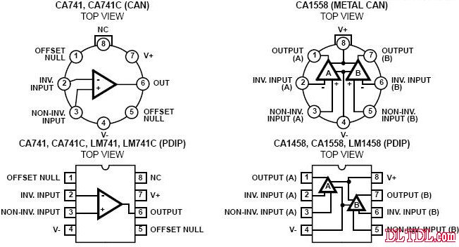
Figure 1 CA741C, CA741, LM741 package pin diagram Figure 2 CA1458, CA1558, LM1458 package pin function diagram
The picture above shows the metal can package. The picture below shows the DIP plastic package.
CA741, CA741C, LM741, LM741C chip pin and work instructions:
1 and 5 are biased (zeroed), 2 is forward input, 3 is reverse input, 4 is grounded, 6 is output, 7 is connected to power, 8 is empty
CA1458, CA1558, LM1458: Chip Pins and Job Description
1 output A 2 reverse input A 3 forward input A 4 ground 5 forward input B 6 reverse input B 7 output B 8 power +
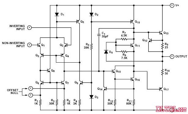
Figure 3 internal circuit diagram
Absolute Maximum Ratings Absolute Maximum Ratings
Parameter item Value unit Power supply voltage CA741C, CA1458, LM741C, LM145836VCA741, CA1558, LM741 44VDifferential Input Voltage differential input voltage 30VInput Voltage input voltage type +/---Maximum Junction Temperature (Plastic Package) Maximum junction temperature (plastic package) -150 °C Maximum Junction Temperature (Can Package) Maximum junction temperature (metal can package) -175 °C Temperature Range Operating Temperature Range CA741, CA1558, LM741-55 - 125 °C CA741C, CA1458, LM741C, LM1458 0-70 °C
Ordering Information Ordering Information
PART NUMBER part number
TEMP temperature. RANGE (oC) PACKAGE package PKG. NO. CA0741E -55 to 125 8 Ld PDIP single op amp E8.3 CA0741CE 0 to 70 8 Ld PDIP single op amp E8.3 CA1458E 0 to 70 8 Ld PDIP dual op amp E8.3 CA1558E -55 to 125 8 Ld PDIP Dual Op Amp E8.3 CA0741T -55 to 125 8 Pin Metal Can Single Op Amp T8.C CA0741CT 0 to 70 8 Pin Metal Can Single Op Amp T8.C CA1558T -55 to 125 8 Pin Metal Can Dual Op Amp T8.C LM741N -55 to 125 8 Ld PDIP Single Op Amp E8.3 LM741CN 0 to 70 8 Ld PDIP Single Op Amp E8.3 LM1458N 0 to 70 8 Ld PDIP Dual Op Amp E8. 3
Electrical Specifications Typical Values ​​Intended Only for Design Guidance, VSUPPLY = ±15V Electrical Specifications Typical values ​​are for design guidance only, VSUPPLY = ± 15V
PARAMETER parameter
SYMBOL symbol
TEST CONDITIONS test conditions
TYPICAL VALUE (ALL TYPES) ​​typical (all types)
UNITS unit
Input Capacitance Input Capacitor CI -1.4
pF
Offset Voltage Adjustment Range Offset Voltage Adjustment Range--±15
mV
Output Resistance Output Resistance RO -75
Ω
Output Short Circuit Current Output Short Circuit Current -25
mA
Transient Response Rise Time Transient response rise time tr unity gain, VI = 20mV, RL = 2kΩ, CL ≤ 100pF 0.3
Ss
Overshoot Overshoot Voltage OS 5.0
%
Slew Rate (Closed Loop) Slew Rate (Closed Loop) SR RL ≥ 2kΩ 0.5
V/μs
Gain Bandwidth Product Bandwidth Gain GBWP RL = 12kΩ 0.9
MHz
Electrical Specifications For Equipment Design, VSUPPLY = ±15V Electrical Specifications Equipment Design, VSUPPLY = ± 15V
PARAMETER parameter
TEST CONDITIONS test conditions
TEMP temperature (°C)
(NOTE 4) CA741, CA1558, LM741 (NOTE 4) CA741C, CA1458, LM741C, LM1458
UNITS unit
Typical Maximum Minimum Maximum Minimum Typical Input Offset Voltage input offset voltage RS ≤ 10kΩ 25 -1 5 -2 6
mV
Full -1 6 --7.5 mV Input Common Mode Voltage Range Input Common Mode Voltage Range -25 ---±12 ±13 -V Full ±12 ±13 ----V Common Mode Rejection Ratio Common Mode Rejection Ratio RS ≤ 10kΩ 25 ---70 90 -dB Full 70 90 ----dB Power Supply Rejection Ratio Power Supply Rejection Ratio RS ≤ 10kΩ 25 ----30 150 μV/V Full -30 150 ---μV/V Input Resistance Input Impedance -25 0.3 2 -0.3 2 -MΩ
Electrical Specifications For Equipment Design, VSUPPLY = ±15V (Continued) Electrical Specifications Equipment Design, VSUPPLY = ± 15V
PARAMETER parameter TEST CONDITIONS test condition TEMP temperature (°C)
(NOTE 4) CA741, CA1558, LM741
(NOTE 4) CA741C, CA1458, LM741C, LM1458
UNITS unit
Minimum Maximum Minimum Typical Typical
maximum
Input Bias Current Input Bias Current -25 -80 500 -80 500 nA Full -----800 nA -55 -300 1500 ---nA 125 -30 500 ---nA Input Offset Current Input Offset Current -25 - 20 200 -20 200 nA Full -----300 nA -55 -85 500 ---nA 125 -7 200 ---nA Large Signal Voltage Gain Large Signal Voltage Gain RL ≥ 2kΩ25 50,000 200,000 -20,000 200,000 -V/ V VO = ±10V Full 25,000 --15,000 --V/V Output Voltage Swing output voltage swing RL ≥10kΩ 25 ---±12 ±14 -V Full ±12 ±14 ----V RL ≥ 2kΩ 25 - --±10 ±13 -V Full ±10 ±13 -±10 ±13 -V Supply Current Supply current -25 -1.7 2.8 -1.7 2.8 mA -55 -2 3.3 ---
With the improvement of people's quality of life, people's lifestyles have also become varied. Different kinds of recreational products are starting to appear in people's lives, such as electronic cigarettes. The emergence of e-cigarettes represents a part of young people's thinking and means that electronic products are beginning to show a trend towards diversity.
simply replace the pods. The Pod system uses an integrated pod rather than a tank for higher nicotine strength and provides low power traction. the Pod system is rechargeable and has a longer life and higher battery capacity than disposable electronic cigarettes.
Our company Pod system has a built-in 380mAh battery and a USB charging port on the bottom. In comparison, the Pod system has a built-in battery of only 180mAh, but the Pod system charges much faster.
Our electronic cigarettes are of rechargeable construction. The first time you use the charger to charge, it is recommended to use up the remaining power before filling up, this is to ensure the performance of the battery.
Vape Pod System Oem,Vape Pod Oem,Close Pod Oem,Thc Pod Disposable
Shenzhen MASON VAP Technology Co., Ltd. , https://www.disposablevapepenfactory.com