Analysis of remote control technology of oscilloscope by computer labview
We know that digital oscilloscopes can accurately capture various periodic signals and non-periodic signals. Digital oscilloscopes have become one of the most important devices for signal acquisition, recording and analysis in scientific research experiments and engineering projects. In many cases, the data collected by the digital oscilloscope needs to be processed and analyzed, and the requirements for remote automatic testing and analysis are finally completed. Therefore, remote automatic control of the oscilloscope, automatic operation of the various functions of the oscilloscope and processing of data has become an essential part of many scientific research experiments and engineering projects. Recently, I have often received many engineers' inquiries about how to control the oscilloscope's phone. Let's talk about the steps and methods of computer-controlled oscilloscopes, and use examples to analyze and explain.
1. System hardware architecture
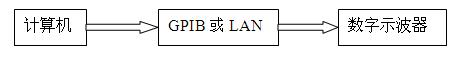
Figure 1 system hardware architecture diagram
The computer connects to the oscilloscope through a GPIB or LAN (network port) to control the oscilloscope. The hardware architecture of the system is shown in Figure 1.
2. System software architecture
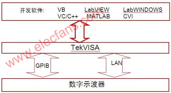
Figure 2 system software architecture diagram
Figure 2 is a system software architecture diagram of a computer-controlled oscilloscope. The entire software development and software development environment are all on the Windows operating system platform. The application is written to control the oscilloscope via TekVISA.
3. Computer controlled oscilloscope step example (taking LAN port control as an example, development software: labview)
The following is a detailed description of how the computer programs the oscilloscope.
3.1 Selection of development software
There are many kinds of the most popular analysis and development software on the market. There are VC/VC++, VB/VBA, Matlab, Labview, LabWindow CVI and other development software, which are selected according to personal hobbies and familiarity with a certain software.
3.2 Installing the driver
TekVISA is a VISA library developed by Tektronix and can be downloaded for free from Tektronix' website. If it is an oscilloscope from another company, you can also use the TekVISA software. After TekVISA runs, it will automatically find the LAN and GPIB interface devices connected to the network, and display them in the prompt box, as shown in Figure 3. According to different IP addresses, different instruments can be distinguished.
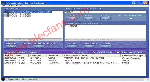
Figure 3 TekVISA automatically finds the instrument interface
3.3 Selection of control interface
There are many interfaces for connecting the computer to the oscilloscope, mainly including GPIB, LAN, USB and other interfaces.
a. .LAN [TCPIP::192.168.0.188::INSTR]
b. GPIB [GPIB0::1::INSTR]
c. USB [USB::0X1234::125::A22-5::INSTR](DPO4K/3K/AFG3K)
3.4. Basic settings of oscilloscope and PC (taking LAN port as an example)
a. Set the IP address of the oscilloscope, for example: 192.168.0.168
b. Set the IP address of the PC, for example: 192.168.0.188
c. Turn off the oscilloscope and PC's Windows and anti-virus software firewall
3.5 Start TekVISA and make related settings
a. Change the communication interface of the oscilloscope to LAN, as shown in Figure 4.
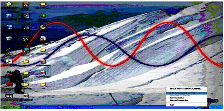
Figure 4 The communication interface of the oscilloscope is changed to LAN
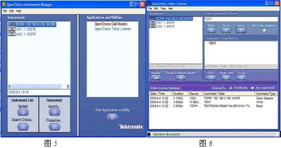
b. Open the TekVISA Instrument Manager on your PC, see Figure 5 and Figure 6, to see if the PC and the oscilloscope are connected and if an oscilloscope is found.
3.6 Start LABVIEW and start writing control program
a. Start labview, open the Front Panel of labview, and write the relevant software operation interface, as shown in Figure 7.
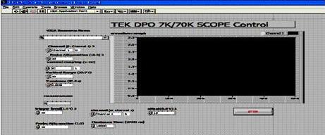
Figure 7 labview control oscilloscope software operation interface
b. Open the block diagram programming interface of labview to write the program to control the oscilloscope.
c. Create an object, as shown in Figure 8.
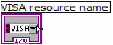
Figure 8
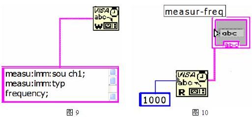
d. Set the oscilloscope parameters, set the oscilloscope acquisition mode, oscilloscope channel, vertical resolution, sampling rate, trigger type, record length and other parameters according to the actual measurement requirements and subsequent data processing requirements, and the corresponding measurement parameters. Figure 9 is to set the oscilloscope to automatically measure the frequency. Figure 10 automatically reads the oscilloscope's measured value.
e. After the oscilloscope meets the trigger condition, collect the data and display the collected data on the software interface. See Figure 11 and Figure 12.
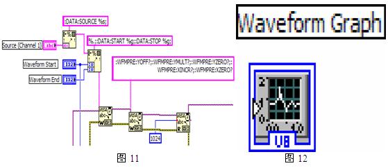
In this way, a complete labview control oscilloscope program is written, engineers can also add data processing part according to their own application needs.
1. System hardware architecture
Figure 1 system hardware architecture diagram
The computer connects to the oscilloscope through a GPIB or LAN (network port) to control the oscilloscope. The hardware architecture of the system is shown in Figure 1.
2. System software architecture
Figure 2 system software architecture diagram
Figure 2 is a system software architecture diagram of a computer-controlled oscilloscope. The entire software development and software development environment are all on the Windows operating system platform. The application is written to control the oscilloscope via TekVISA.
3. Computer controlled oscilloscope step example (taking LAN port control as an example, development software: labview)
The following is a detailed description of how the computer programs the oscilloscope.
3.1 Selection of development software
There are many kinds of the most popular analysis and development software on the market. There are VC/VC++, VB/VBA, Matlab, Labview, LabWindow CVI and other development software, which are selected according to personal hobbies and familiarity with a certain software.
3.2 Installing the driver
TekVISA is a VISA library developed by Tektronix and can be downloaded for free from Tektronix' website. If it is an oscilloscope from another company, you can also use the TekVISA software. After TekVISA runs, it will automatically find the LAN and GPIB interface devices connected to the network, and display them in the prompt box, as shown in Figure 3. According to different IP addresses, different instruments can be distinguished.
Figure 3 TekVISA automatically finds the instrument interface
3.3 Selection of control interface
There are many interfaces for connecting the computer to the oscilloscope, mainly including GPIB, LAN, USB and other interfaces.
a. .LAN [TCPIP::192.168.0.188::INSTR]
b. GPIB [GPIB0::1::INSTR]
c. USB [USB::0X1234::125::A22-5::INSTR](DPO4K/3K/AFG3K)
3.4. Basic settings of oscilloscope and PC (taking LAN port as an example)
a. Set the IP address of the oscilloscope, for example: 192.168.0.168
b. Set the IP address of the PC, for example: 192.168.0.188
c. Turn off the oscilloscope and PC's Windows and anti-virus software firewall
3.5 Start TekVISA and make related settings
a. Change the communication interface of the oscilloscope to LAN, as shown in Figure 4.
Figure 4 The communication interface of the oscilloscope is changed to LAN
b. Open the TekVISA Instrument Manager on your PC, see Figure 5 and Figure 6, to see if the PC and the oscilloscope are connected and if an oscilloscope is found.
3.6 Start LABVIEW and start writing control program
a. Start labview, open the Front Panel of labview, and write the relevant software operation interface, as shown in Figure 7.
Figure 7 labview control oscilloscope software operation interface
b. Open the block diagram programming interface of labview to write the program to control the oscilloscope.
c. Create an object, as shown in Figure 8.
Figure 8
d. Set the oscilloscope parameters, set the oscilloscope acquisition mode, oscilloscope channel, vertical resolution, sampling rate, trigger type, record length and other parameters according to the actual measurement requirements and subsequent data processing requirements, and the corresponding measurement parameters. Figure 9 is to set the oscilloscope to automatically measure the frequency. Figure 10 automatically reads the oscilloscope's measured value.
e. After the oscilloscope meets the trigger condition, collect the data and display the collected data on the software interface. See Figure 11 and Figure 12.
In this way, a complete labview control oscilloscope program is written, engineers can also add data processing part according to their own application needs.
Product application:
â– Products for commercial,household,lighting
Product features:
â– Good contact
--The contact point composite silver layer is designed to reduce
the contact resistance and reduce the temperature rise.
â– Ultra high strength,impact resistance and thermal stability
--The upper cover is made of high quality polycarbonate and the
bottom shell is made of PA6
â– Chemical corrosion resistance
-- Fingerprint-resistant zinc plated mounting brackets
â– Grounding
--One-piece grounding design
Switch UL,Decorative Switch UL,Electrical Switch UL,White Switch UL
Hoojet Electric Appliance Co.,Ltd , http://www.hoojetgfci.com