Implementation Scheme of Multi-Chip Digital Signal Processing System Based on ADSP-TS101S
Abstract: This paper is based on the implementation of ADSP-TS101S multi-chip digital signal processing system. The system is applied to a radar signal processor. Firstly, the paper first introduces the composition of the signal processing system composed of multiple TIgerSHARC DSP chips. Secondly, it estimates the calculation amount of the system and the required calculation time. Finally, the method of generating reset signal and parallel-serial conversion function by CPLD is described.
Introduction With the continuous improvement of real-time signal processing requirements and the rapid development of large-scale integrated circuits, DSP, which is the core and symbol of digital signal processing, has been rapidly developed and applied. This article is based on a DSP from Analog Devices, TIgerSHARC, which provides a detailed description of a specific implementation in a signal processing system.
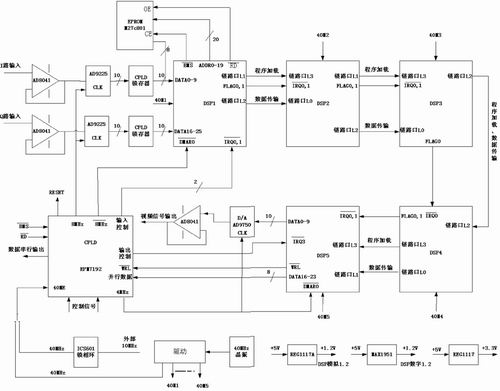
Figure 1 Signal processor block diagram
System design and various parts of the function introduction This system is a radar signal processor, through the ADC read IF data, DSP1, DSP2 complete data pulse compression and sidelobe suppression, DSP3, DSP4 complete data accumulation and model, DSP5 implementation Normalization of video data, output of video data through a DAC, and transmission of parallel data. The system structure is shown in Figure 1.
In this system, the ADC adopts AD9225 with 12 effective data bits and 25MSPS conversion rate. The two analog signals of I and Q are converted into digital signals at a certain sampling rate, and the upper 10 bits are sent to the DSP.
This system uses TIgerSHARC DSP, the maximum operating speed of 300MHz, the core instruction cycle is 3.3ns, can execute up to 4 instructions per cycle, 24 16-bit fixed-point operations and 6 floating-point operations, and contains 6MB of on-chip SRAM With high storage and computing performance, it has high application value in the field of signal processing. In order to simplify the system hardware and reduce the DSP inter-chip connection, the system's five DSPs are connected in a loosely coupled link. DSP1 reads the I and Q data of the intermediate frequency demodulation by external DMA mode, and DSP1 performs pulse compression (matching filtering) on ​​the read part of the data, and sends the processed data and unprocessed data to the link port 2 to DSP2. DSP2 performs pulse compression on the remaining data. DSP2 sends all processed data to DSP3. Due to the accumulation of tens of frames, the amount of data is large, and DSP3 and DSP4 respectively undertake half of the data accumulation and modulo operation. DSP4 sends the modulo result to DSP5. The DSP 5 normalizes the data to generate video data, and the video data is sent out through the external port in a DMA manner. Parallel data is also sent to the CPLD in different operating modes.
Program loading: This system uses the EPROM program to guide. When using the link port of the TIgerSHARC DSP for data transfer, each word must be set with 4 words, the number of transmitted words must be a multiple of 4, and the data start address must be aligned every 4 words. Therefore, the sender DSP must read in each of the 32 32-bit words from the EPROM and send them through the load link.
The DAC uses a high-speed device, the AD9750, with a 10-bit effective data bit and a 125MSPS slew rate to convert video data to an analog signal at a fixed rate.
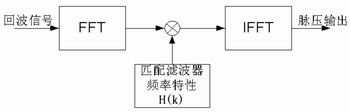
Figure 2 block diagram of the pulse compression filter algorithm
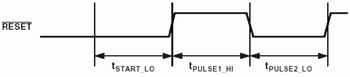
Figure 3 Power-on reset waveform of TigerSHARC DSP
The CPLD performs functions such as data latching, DSP reset signal generation, and conversion of parallel data to a serial data output of a certain baud rate (serial output satisfies the RS-232 standard).
Clock: The DSP internally uses the clock generated by the 40MHz crystal oscillator inside the board. The A/D sampling clock should be phase-locked with the system clock. Therefore, the 10MHz system clock is phase-locked to 40MHz via ICS 601M, and the CPLD is input to the CPLD through the 40ME pin. The A/D sampling clock signal is generated after the frequency division, and the D/A sampling working clock is also It is produced by it. When the board is debugged, only the clock in the board can be used. Therefore, the 40ME should be selected with a jumper.
Power: The TigerSHARC DSP has three power supplies, a digital 3.3V for I/O supply, a digital 1.2V for DSP core supply, and an analog 1.2V for internal phase-locked loop and multiplier circuit power. The TigerSHARC DSP requires digital 3.3V and 1.2V to be powered up simultaneously. If it is not possible to strictly synchronize, ensure that the core power supply is 1.2V first, and the I/O power supply is powered up after 3.3V. The system has a large capacitance on the digital 3.3V input terminal, and a digital 1.2V input terminal with a small capacitor, so that the 3.3V charging time is greater than 1.2V charging time, which solves the problem of power supply sequencing. The digital 1.2 V power supplies of each DSP are converted from a +5V to a 1.2V supply by a MAX1951. All DSP analog 1.2V power supplies are unified by a REG1117A to convert the analog +5V to a 1.2V supply. The 5-chip DSP I/O 3.3V power supply is converted from a REG1117 digital +5V to a 3.3V unified supply.
System calculation analysis and calculation time estimation According to the task of signal radar processing, the following is a detailed analysis of the calculation amount of each component of the system to estimate the required calculation time. (Signal processing should be less than 1ms per frame)
Pulse compression The pulse compression filter is implemented by FFT technology. The algorithm is shown in Figure 2. 512, 1024, and 4096 point complex FFTs are required depending on the operation. After the complex FFT is completed, it must be multiplied by the pre-stored matched filter coefficients H(k). 512, 1024, and 4096 complex multiplications are required. The multiplication results also require 512, 1024, and 4096 complex IFFTs to obtain Pulse pressure results. TS101 does 1024-point complex FFT (IFFT) in the practical application of this system takes about 50ms (working at 200MHz). You can make full use of TS101 dual operation block, single instruction multiple data (SIMD) feature, and perform complex multiplication of two distance units at the same time. It takes only 15ms to complete 1024 complex multiplication. This completes pulse compression at 512, 1024, and 4096 points, requiring 60ms, 120ms, and 460ms, respectively. Since DSP1 uses DMA to segment each frame of data and does not have enough time to perform 4096-point pulse compression, it is placed in DSP2.
Sidelobe suppression The side-valve suppression is performed on the two-phase code by the time-domain synthesis method, and the side-lobe suppression coefficient is integrated in the matched filter coefficient of the pulse compression, thereby achieving the effect of suppressing the side lobes. The algorithm is implemented on the basis of pulse compression, and has no additional influence on the calculation amount and time of the DSP.
Accumulation Accumulation adopts the sliding window accumulation method, and the calculation amount is small, and TS101 realizes a large time surplus. The actual requirement is to accumulate at least 35 frames. Each cycle I and Q has a total of 2×3200 points, and requires about 2×3200×35=224K bytes of storage space. Therefore, the accumulation operation is completed in DSP3 and DSP4, respectively.
CPLD generates reset signal and implementation of parallel-to-serial conversion function
The power-on reset mode of TigerSHARC DSP is special, and should be paid attention to in design. This system uses Altera's CPLD EPM7192 to generate power-on reset waveform and timing control. The power-on reset waveform requirements are shown in Figure 3.
Here should be noted:
tstart_LO must be greater than 1ms after the power supply is stable;
tpulse1_HI must be greater than 50 system clock cycles, less than 100 system clock cycles;
tpulse2_LO must be greater than 100 system clock cycles.
Normal reset after DSP power-up: Low-level duration must be greater than 100 system clock cycles.
Implementation of the parallel-to-serial conversion function Parallel data is sent from the DSP to the CPLD, which is converted to serial data by the CPLD and sent at a fixed baud rate. The program written in the AHDL language supported by MAX+plusII has realized the parallel-to-serial conversion function, which is flexible, simple, and extensible. The specific procedures will not be described again.
Conclusion The implementation of the multi-chip TigerSHARC DSP described in this paper in the real-time signal processing system has been successfully applied to the improvement of the signal processor of a radar. Structurally, the original three boards are combined into one piece; the number of chips is reduced from a dozen (ADSP21062) to five (ADSP TS101S). Based on the completion of the original functions, some functions to improve performance are also implemented. And the power consumption of the new system is greatly reduced compared with the original, and the heat dissipation is also significantly reduced. Practice shows that the system consisting of TigerSHARC DSP has simple hardware structure, easy software writing, low cost and high engineering application value.
we are professional battery manufacturer in heated clothing industry over 10 years. we make all kinds of li ion battery packs for heated jacket, wlectric jacket, heated sweatshirt, heated motorcycle gear, heated boots, heated shirt, heated slippers, electric heated jacket, heated pants, battery heated jacket, heated glove liners, heated ski gloves, heated coat womens, heated vest womens, heated underwear, electric clothing, heated motorcycle jacket, heated gloves and socks, heated hunting jacket, electrician pants, heated hat, battery operated gloves.
we offer the most extensive models for heating clothing industry, our heating clothing batteries range from 3.7v to 14.8v most popular models, capacity from 1800mah to 10000mah, with LED light and switches to display remaining power level and set output levels. OEM/ODM accepted and we are specilisted in design these batteries, providing industry design, pcb design, tooling design, moulding service, prototyping, and flexiable small quantity manufacturing.

Heated Clothing Battery,Heated Jacket Battery,Heated Gloves Battery,Heated Vest Battery
Asarke Industry Co., Limited , http://www.asarke-industry.com