How to properly measure power supply ripple with an oscilloscope
Power supply ripple testing is an important parameter in power quality detection, but how to accurately measure power supply ripple has become a difficult problem for engineers. How can we break this problem? In fact, the public is looking for it, and when it comes back, the method is in a dim light.
Since the DC stabilized power supply is generally formed by the rectification, filtering, and voltage regulation of the AC power supply, it is inevitable that there is some AC component in the DC voltage, and the AC component superimposed on the DC stabilized voltage. It is called ripple.
First, the incorrect ripple test
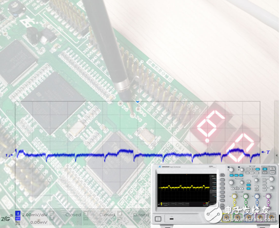
Connect a 3.3V power supply signal to the ZDS2024 Plus oscilloscope. Use the X10 file to measure the power supply ripple. Click [Auto Setup] to adjust the horizontal time base, vertical scale and vertical offset. It is shown in Figure 1 below.
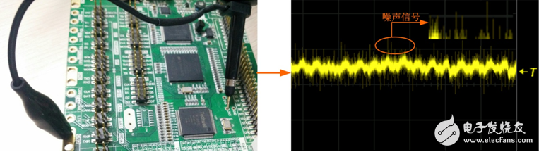
Figure 1 Incorrect ripple measurement method
As can be seen from the figure, the measured waveform is mixed with many noises and clutter, and the DC and AC waveforms are mixed together. There is no way to clearly observe the ripple, which makes it impossible to accurately measure the ripple value. Many engineers measure ripple in this situation because they do not have the correct ripple measurement method.
Second, the correct power ripple test method
1. First, the probe should select the appropriate gear position. If the voltage is relatively large, or the bandwidth requirement is relatively high, the X10 gear can be used. In normal cases, it is recommended to use the X1 gear to avoid unnecessary noise attenuation affecting the ripple measurement.
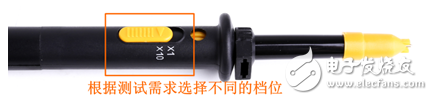
Figure 2 probe gear selection
2, the ripple belongs to the AC component, so the "channel coupling" mode can use the "AC" mode to limit the input of the DC signal, as shown in Figure 3.
3. The “Bandwidth Limit†function can be used appropriately, and the “20MHz†bandwidth limit can be selected to filter unnecessary high-frequency noise, as shown in Figure 3.
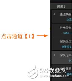
Figure 3 channel interface parameter settings
4. In addition to this, it is more important to avoid interference with signals such as electromagnetic radiation. Therefore, it is recommended to use “grounding spring†to ground during measurement to avoid unnecessary interference caused by long grounding wires.
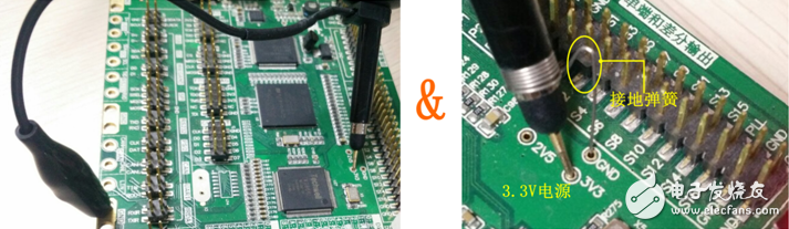
Figure 4 Comparison of grounding methods
5. The trigger mode can be edge triggered, and the trigger mode can be in the Auto/Normal state.
6. Adjust the horizontal time base, vertical gear position and vertical offset appropriately so that the waveform signal is displayed in the center of the screen with better results.
The specific captured ripple is shown in Figure 5 below.
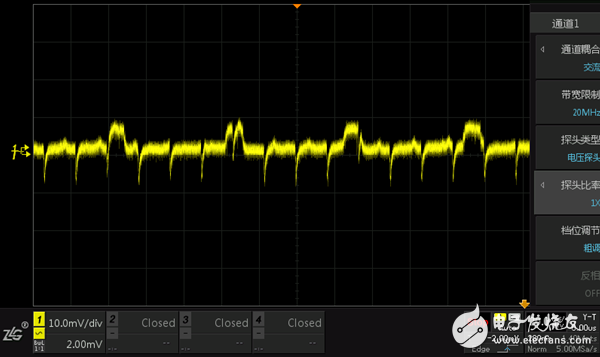
Figure 5 Correctly captured ripple
As can be seen from Figure 5, the correct ripple measurement method can clearly capture the normal ripple, reduce the unnecessary noise and the effect of clutter on the ripple, basically a clean ripple. Power ripple measurement on this basis allows you to more accurately measure the ripple value and accurately estimate the power quality.
Ripple test is generally expressed by peak-to-peak value. You can use [measure] for automatic measurement. The following screenshot shows the ZDS2000 series oscilloscope. It can support 51 kinds of true parameter measurement and statistics functions. The parameters of ripple are measured based on the full memory depth. Or you can use the "One-Click Cursor" for manual measurement, as shown in Figure 6 below.
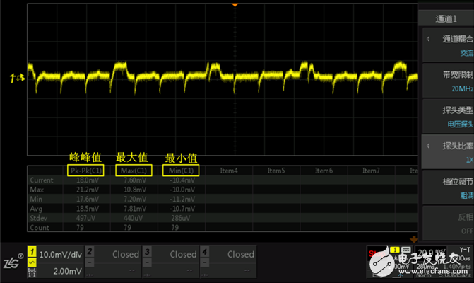
Figure 6 Ripple measurement data
Third, the measurement results analysis
It can be seen from the measurement that the peak-to-peak value of the power supply ripple is 18mv. Intel specifies in the ATX12V specification that the peak-to-peak value of the +12V output ripple must not exceed 120mv, and the peak-to-peak value of +3.3V and +5V ripple must not exceed 50mv. The smaller the power supply, the higher the quality.
5V 2A USB Power Adapter,Output 5V 2A Power Adapter,USB Power Adapter 5V,Power Strip With USB
Dongguan baiyou electronic co.,ltd , https://www.dgbaiyou.com