Realization of CAN bus communication in electric vehicle body network
Realization of CAN bus communication in electric vehicle body network
With the increasing awareness of environmental protection and the shortage of oil in the world, pure electric vehicles [1] have ushered in a period of rapid development. For electric vehicles, in addition to requiring good power and mileage, they also need to have various performances of ordinary cars, which makes electronic devices in electric vehicles more and more [2], and automobile wiring harnesses are also getting more and more The complexity, the weight of the wiring harness and the required installation space are also getting larger and larger, and the traditional wiring method of automobiles cannot meet the requirements of electric vehicles. Therefore, the automotive network came into being, and has become an important development direction of automotive electronic technology. Automobile network mainly refers to the establishment of a communication network between various automotive electronic devices and controllers through the bus technology, which can greatly simplify wiring, facilitate maintenance, improve wire utilization, and also greatly reduce manufacturing costs. CAN bus [3] is a bus type widely used in automotive networks now, it has the characteristics of simple structure, low cost and extremely high reliability. But for electric vehicles, there is no CAN bus communication protocol specifically for electric vehicles. Based on the study of the CAN open protocol, this paper develops a bus communication protocol for electric vehicle bodies, and implements network data communication through LABVIEW [4].
1 Introduction
The CAN bus is a serial communication network that effectively supports distributed control or real-time control, and its applications range from high-speed networks to low-cost multi-line networks. The CAN bus has the following characteristics:
(1) CAN is by far the only field bus with international standards.
(2) CAN works in multi-master mode, any node on the network can actively send information to other nodes on the network at any time, without dividing the master and slave.
(3) On the message identifier, the nodes on the CAN are divided into different priorities, which can meet different real-time requirements, and the data with high priority can be transmitted within 134 us at most.
(4) CAN uses non-destructive bus arbitration technology.
(5) The CAN node can achieve point-to-point, point-to-multipoint and global broadcast transmission methods only by filtering the identifier of the message, without special "scheduling".
(6) The direct communication distance of CAN is up to 10 K meters; the communication rate is up to 1 Mbps.
(7) The number of nodes on CAN mainly depends on the bus driving circuit, and currently up to more than 110.
(8) The message uses a short frame structure, the transmission time is short, and the probability of interference is low, which reduces the data error rate.
(9) Each frame of CAN information has CRC check and other error detection measures, with excellent error detection effect.
(10) The CAN communication medium can be twisted pair, coaxial cable or optical fiber.
(11) The CAN node has an auto-shutdown output function in severe cases so that the operation of other nodes on the bus is not affected.
(12) The CAN bus has a high performance-price ratio.
2. Topological structure of the body network For the electric vehicle body network [5], there are many electronic devices, and the location distribution is messy. In order to facilitate the management of the entire network, the entire body network can be divided into different nodes according to different topological structures. The division of network nodes is based on the principle of block division. Electronic devices in the nodes can communicate with each other, and electronic devices in different areas communicate through different network nodes. Based on the analysis of the equipment of the electric vehicle body, the body network is divided into dashboard nodes, left front nodes, right front nodes, left rear nodes, and right rear nodes.
For the body network, electronic devices do not have high requirements for communication speed. Therefore, according to the SAE body network definition of the American Society of Engineers, choose a type B bus with a transmission rate of 10-125 kbps. The network topology is shown in Figure 1. Show: 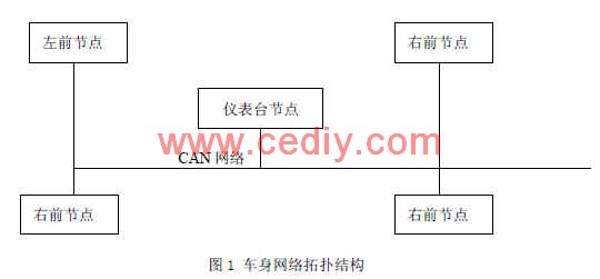
3. Communication protocol message design The general message format of CAN bus is adopted [6] The maximum data length of each frame is 8 bytes.
The main task of messages in the communication protocol is to send and receive messages, and the messages are received and sent in the format of data frames [7]. The data field of the data frame can send or receive 8 bytes of message content. Each byte has 8 bits, and only 1 bit can be sent or received at a time. The communication protocol message format is shown in Table 1. 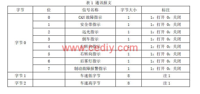
4. Protocol realization based on LABVIEW The hardware uses MC9S12DP51216 single chip microcomputer [7]. MC9S12DP51216 single-chip microcomputer bus adopts twisted pair and desktop PC.
4.1 Defining the data structure In LABVIEW, the Virtual CAN Interface (VCI) function library is an application program interface specifically provided for the use of ZLGCAN devices on the PC. These library functions can be used directly from LABVIEW. First create the VCI function Kud data structure, define the data type as cluster, and call the library function at the same time [8].
The program of this system realizes the sending and receiving of data, and displays the received and sent data in the list on the front panel through the CAN bus. The program contains 3 main While loops: main loop, send data loop and receive data loop. These three loops run in parallel and are independent of each other. The main loop handles the interface that interacts with the user. It uses an event-driven mechanism to handle user operations on the front panel, and communicates with the send data loop and the receive data loop through user events. It contains the following functions: turn on / off the device, timeout, start CAN, reset CAN, read device information, read CAN status, read error information and clear the buffer.
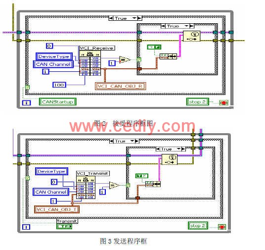
4.2 Implementation of data sending and receiving functions To receive and send data through the buttons of the control panel, call the VCI function, and at the same time display the data in real time. The program block diagram is shown in Figure 2 and Figure 3.
4.3 Drive module design
Driver modules include timeout module, stop module, OpenDevice module design, StartCAN module design, ResetCAN module design, Clear Buffer module design, GetBoradInfo module design, GetErrorInfo module design, GetStatus module design, TREvent module design, etc . Each module realizes the required functions by designing control keys in the control panel and calling sub-functions.
The block diagram of the TREvent module is shown in Figure 4. This module is mainly used to display the data sent and received. 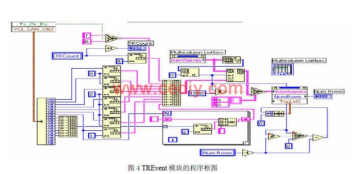
5. System testing
5.1 Establish the control panel and display panel The body network system should correctly reflect the communication status, first of all, it is necessary to collect many signals on the body CAN bus of the car in the working state. These signals can be divided into two categories: open-light signals and analog signals.
The switch signal is also called digital signal, mainly including low beam light switch, high beam light switch, brake light switch, fog light switch, turn signal switch, air conditioner switch, wiper switch. There are also some indication signals that are bright and need to be transmitted through the CAN network to display the amount in the meter. These quantities include CAN fault indication, seat belt indication, high beam indication, reverse indication, left turn indication, right turn indication, rear fog lamp indication, brake failure alarm indication, parking indication, etc.
There are also some analog signals in the body network, mainly including motor speed, vehicle speed, battery power, battery voltage, battery temperature, etc.
The control panel and display panel of the switch module are established through the LABVIEW software. Through the buttons on the control panel, you can send the corresponding data and display the corresponding signal on the display panel. 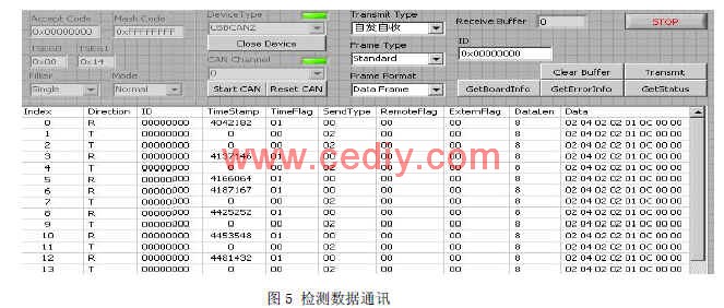
5.2 Data receiving and sending detection To detect the sending and receiving of data, the behavior of sending and receiving data set in LABVIEW is spontaneous and self-receiving [9]. Start CAN, the indicator light is on, click the send button, the data is sent out in the form of spontaneous self-receiving [10], as shown in Figure 5. 6. Conclusion In this paper, the body network of electric vehicles is established according to the characteristics of electric vehicles. Based on the analysis of the CAN bus, the application layer communication protocol is established. Use LABVIEW software to write the upper computer software for CAN network communication. In order to verify the data transmission and reception of the communication, simulation is performed in the LABVIEW software. After inspection, the system can well meet the communication requirements of the electric vehicle body network.
The author's innovation:
The CAN bus technology is used to establish a pure electric vehicle body network, and the network connection is realized through LABVIEW software. And through the system communication test, the feasibility of the network is verified.
Introduction of EMI Filter In Medical Devices
Rated currents: 0.5 to 300A
Various types of connections: pin, IEC inlet, wire, solder lug, thread, terminal block, etc.
Custom specific versions available on request
Features of Medical Device FiltersExcellent common and differential mode attenuation effect, guarantees the accuracy and reliability of medical equipment;
Very low leakage current, fully comply with the safety requirement of medical devices.
Items with IEC inlet or pin connection available, compact structure, easy to install, high cost performance;
Three-phase versions are suitable for high power medical devices, which are safe and effective.

Ac Noise Filter,EMI Filter In Medical Devices,EMI Filter For Medical Appliance,Medical Device Filters
Jinan Filtemc Electronic Equipment Co., Ltd. , https://www.chinaemifilter.com