New low capacitance EMI filter brings stronger anti-interference performance to mobile phones
New low capacitance EMI filter brings stronger anti-interference performance to mobile phones
As the video resolution of LCDs and cameras in mobile phones increases, the frequency of data operations will exceed 40 MHz. For the suppression of wireless EMI and ESD, traditional filter solutions have reached their technical limits. In order to adapt to the increase in data rate without interrupting the video signal, designers can choose the new low capacitance, high filtering performance EMI filter discussed in this article.
As the wireless market continues to develop, the next generation of mobile phones will have more features, such as multiple color screens (each mobile phone has at least two color screens) and high-resolution cameras with more than megapixels.

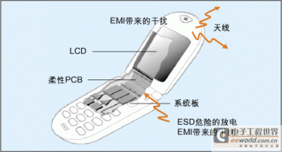
Figure 1: Noise and ESD transmission path around the LCD module.
Still driven by the trend of compact design, implementing high-resolution LCDs and cameras will face designers with multiple challenges. One of the main design considerations is the sensitivity of these new modules to electromagnetic interference (EMI).
For many current mobile phones (especially clamshell phones), the color LCD or camera CMOS sensor is connected to the baseband controller through a flexible or long trace PCB connected between the two main parts of the phone (upper and lower).
On the one hand, the connection line will be disturbed by the parasitic GSM / CDMA frequency radiated by the antenna. On the other hand, due to the introduction of high-resolution CMOS sensors and TFT modules, digital signals work at higher frequencies, so that the connection line will produce EMI / RFI like an antenna or may cause ESD dangerous events.
In short, in the above two cases, all these EMI and ESD interference will destroy the integrity of the video signal and even damage the baseband controller circuit.
To suppress these EMI emissions and ensure normal data transmission, consider implementing several filter solutions, which can be achieved by using discrete resistive-capacitive filters or integrated EMI filters.

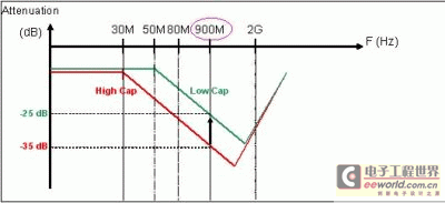
Figure 2: The GSM attenuation frequency corresponds to the filter capacitor.
If the EMI and ESD noise suppression methods take into account design constraints such as board space, high filtering performance at the mobile phone operating frequency, and preservation of signal integrity, the currently known solutions are reaching their technical limits.
Discrete filters cannot provide any space savings for the solution, and they can only provide limited filtering performance for narrow-band attenuation, so most designers are currently considering integrated EMI filters.
In a mobile phone equipped with a high-resolution LCD and an embedded camera, the signal is transmitted from the baseband ASIC to the LCD and the embedded camera through a specific frequency (depending on the resolution).
The higher the video resolution, the higher the frequency of data work. So far, the general data is working at a frequency of about 6 to 20MHz, and the resolution competition will also encourage camera module manufacturers to continue to increase this frequency to 40-60MHz.

Figure 3: New filter unit structure (series resistance is 100 ohms and line capacitance is 17pF).
In order to adapt to the increase in data rate without interrupting the video signal, the designer must choose a filter with low capacitance that is theoretically recommended, that is, the filter cut-off frequency (1 / 2Ï€RC) must be approximately 5 times the clock frequency.
In current wireless terminals, for camera modules with 300,000 to 600,000 pixels, the clock frequency is between 6 and 12 MHz. Therefore, it is recommended to select the filter (upper and lower) cutoff frequency in the range of 30 to 50MHz. Many filter solutions follow this theoretical recommendation, but as the resolution increases and the clock frequency exceeds 40MHz, the filter cutoff frequency must be within 200MHz. Therefore, it is foreseeable that some filter solutions are reaching their limits.
Table 1 shows the comparison of several filter capacitor values ​​with the cutoff frequency, and clock compatibility. This shows that the low-capacitance filter is the most suitable solution for high-frequency, high-speed data signal transmission.
However, the designer knows that there is an unsolvable trade-off between the filter capacitor value and the attenuation characteristics at the GSM / CDMA frequency. The low-capacitance structure will affect the high-frequency performance of the filter, and most low-capacitance filters currently cannot provide attenuation performance better than -25dB at 900MHz. Figure 2 shows the effect of EMI filter capacitors on GSM frequency attenuation.

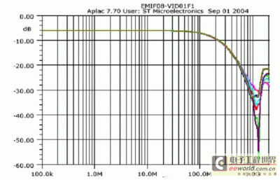
Figure 4: S21 parameter measurement of a new low-capacitance EMI filter.
Low-capacitance EMI filter with improved performance To meet the contradictory requirements of realizing low-capacitance filter while maintaining high filter performance, STMicroelectronics has developed an ultra-low capacitance structure with high-frequency attenuation characteristics at 900MHz New generation EMI filter.
These new EMI filters based on IPAD technology (integrated active and passive devices) use a standard PI filter structure with integrated ESD protection. Figure 3 shows a basic filter unit configuration with series resistance and capacitance.
This new low-capacitance structure is used to provide a cut-off frequency in the 200MHz range and can support data rates with clock frequencies in excess of 40MHz.
Although the diode capacitance has been greatly reduced to 8.5pF, it can provide excellent filtering performance, that is, the attenuation characteristic is better than -35dB in the frequency range of about 900MHz.
Figure 4 shows the S21 parameter index using the basic unit architecture of this filter. The figure shows 35dB attenuation at 900MHz, which is an unprecedented performance achieved by a 17pF line capacitor integrated EMI filter.

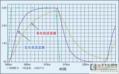
Figure 5: Comparison of 40MHz data transmission test results through high and low capacitance filters.
In addition to the filtering function, the integrated input zener diode can also suppress up to 15kV air discharge ESD impact, reaching the performance level required by the IEC61000-4-2 level 4 industrial standard.
High-speed data compatibility In order not to disturb the video signal, the new low-capacitance filter is designed with optimized line capacitance values ​​to support chipsets with clock frequencies higher than 40MHz.
This structure has only a small effect on the rising and falling edges of the data signal, and there is almost no delay between the input and output of the device.
The input Rt (10-90% rising edge) and Ft (10-90% falling edge) are simulated with a signal of maximum 2.8V and 1ns. The results show that the delay caused by the filter (the difference between the output and the input signal) No more than 1ns. To be sure, even for high-resolution LCD or camera applications, the integrity of the data can be fully maintained.
Figure 5 shows a comparison of the transmission of 3V video signals operating at 40MHz through high and low capacitance filters. It can be found that the delay caused by the high capacitance structure is 5 to 6 times that of the low capacitance structure. In this case, the signal output voltage cannot be received correctly.

Table 1: Corresponding filter solutions for cut-off frequency and clock signal compatibility.
Compared with discrete designs, highly integrated solutions use a flip-chip packaged integrated EMI filter designed with stacked bumps to simplify PCB layout and save up to 80% of board area.
The results show that the line integration rate (PCB area / line number) is about 0.6. This means that these new filters can take up 0.6mm2 of PCB area per line to provide EMI functionality and ESD protection.
It is recommended that this new filter series use 4, 6, and 8 "PI" line configurations to provide design flexibility and meet most high-speed data line design requirements. The PCB area occupied is 2.4mm2, 3.7mm2 and 5.0mm2, so it can be almost completely used in traditional SOT323 plastic package.
ST's new low-capacitance EMI filter supports 4, 6 and 8-wire configurations, each of which includes an RC filter network with Zener diodes on the side. A series resistance of 100 ohms and a line capacitance value of 17 pF are used to achieve a minimum attenuation of 30 dB in the range of 0.8 MHz to 2 GHz. The low capacitance of the devices means they can be used in next-generation LCD displays and camera sensors with clock frequencies in excess of 40MHz.
Simplex SM / MM Fiber Pigtail SC / LC / ST/FC
Pigtails & patch cords can be supplied in a variety of lengths, colors and with a variety of different connector types. Different fiber types and cable diameters are also available on request.
Features of FC/UPC Multimode Fiber Optic Pigtails:
1) Superior qualified standard PC, APC, UPC, SPC polishing;
2) 100% optic test: Insertion Loss: ≤0.3 (PC); ≤0.2 (APC); ≤0.2 (UPC); ≤0.3 (SPC);
3) 100% optic test: Return Loss: ≥45 (PC); ≥60 (APC); ≥55 (UPC); ≥50 (SPC);
4) φ0.9mm, φ2.0mm, φ3.0mm cable optional;
5) Single mode (9125) or multi mode (50/125 or 62.5/125) fiber available;
6) FC, SC, LC, MU, ST, MT-RJ, etc connector
7) Simplex and duplex connector available; 8) Good exchange ability and good durability;
9) Available in fiber bunch, ribbon fan-out, pigtail available;
10) Meets ISO9001, ROHS and Bell core GR 326-core standards;
11) Customized specifications are welcomed.
Applications of FC/UPC Single mode Fiber Optic Pigtails:
1) CATV, metro test equipment;
2) Telecommunication networks;
3) Local area networks (LAN);
4) Wide area networks (WAN);
5) Premise installations;
6) Data processing networks;
7) Video and military active device termination.
Fiber Optic Pigtail,Robbon Optic Pigtail,Bundle Optic Pigtal,Fiber Pigtail
Chengdu Xinruixin Optical Communication Technology Co.,Ltd , https://www.xrxoptic.com