Design and Implementation of Distributed Controller Based on CAN Bus
Design and Implementation of Distributed Controller Based on CAN Bus
In recent years, college students' scientific and technological innovation design activities have become more and more abundant, and designing a special controller for each electromechanical system is not only time-consuming, but also difficult to meet the stability requirements of the system, so it is necessary to provide an open control system platform So that students can conduct secondary development on this platform. Reference [1] moderately proposed an electromechanical controller based on TCP / IP and CORBA, which has a complex architecture and complete functions, which is very suitable for industrial use. For the design requirements of school students, it is necessary to provide a clear principle and a clear architecture The open development system of this article is based on this principle. Students can choose corresponding hardware and software modules according to different design requirements, freely combine, and complete a high reliability control system architecture after some programming.
The executive parts of the electromechanical system include motors, steering gears, hydraulic cylinders, hydraulic motors, etc.The sensing part has contact and non-contact proximity sensors (photoelectric sensors), image sensors (CCD, color discrimination sensors), sound sensors (microphones), etc. If a centralized design method is adopted, it not only improves the requirements for designers, but also makes it difficult to adapt to the constantly changing control requirements. In terms of software design, centralized hardware design will make the software architecture very cumbersome, unable to work together with multiple people, and difficult to maintain. In terms of control system hardware installation, a centralized hardware architecture is likely to increase difficulties in wiring harness. In summary, the use of distributed design can reduce design risks, improve design efficiency, and increase system flexibility.
The control system is divided into three parts: signal input part, central processing part and signal output driving part. The signal input part includes digital signal input and analog signal input, and the signal output drive part designs corresponding drive circuits according to different drive components. The commonly used executive parts of students include DC servo motor, DC motor, pneumatic control valve, etc. The latter two belong to a control mode, so the driving part is mainly DC servo drive and valve drive. Therefore, the distributed control module can be divided into: signal input module, main control module, DC servo motor drive module, pneumatic valve drive module and so on.
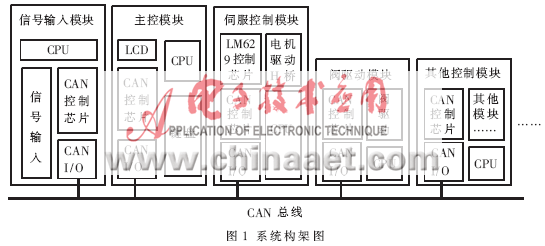
The signal input module is mainly the input and coding of sensor signals, which are divided into digital signal input and analog signal input; the main control module is a platform for information processing, decision-making and human-computer interaction, including keyboard input and LCD output; DC servo motor control drive The module uses LM629 as the motor control chip to complete the PID control of the DC motor through the H-bridge drive; the valve drive module is used to open and close the pneumatic valve and drive the DC motor, so it also uses the H-bridge drive mode. The CAN bus architecture is used between each module (see Figure 1). The control chip adopts P89C58X2, and uses KeilC and CSOS system for algorithm design. The system hardware and software architecture is clear and has good scalability.
1 Hardware circuit architecture
1.1 DC servo motor control
The bus connection is used between P89C58X2 and LM629, that is, the P0 port of the single-chip microcomputer is connected to the data input bit of LM629 through the pull-up resistor. 
 HI is connected to the external interrupt port of the single chip microcomputer, the code disc inputs A, B and IN are connected to the pull-up resistors and then connected to the motor code disc, and the output ports PWM MAG and PWM SIG of the LM629 are connected to the PWM and DIR driven by the H bridge motor The encoder disk and LM629, H bridge and LM629 are separated by high-speed optical isolation 6N137, as shown in Figure 2.

Integrating two LM629 on a single board can make the structure more compact and the algorithm simpler. The LM629 can be easily set to work in speed mode or displacement mode through software.
1.2 CAN bus hardware design
CAN bus is a kind of field bus with high cost performance with international standards. Its maximum transmission speed can reach 1Mb / s, the longest transmission distance can reach 10km, and its performance is stable. It is very suitable for distributed systems with high reliability requirements.
The CAN bus control chip of this system adopts Philips SJA1000, which supports the standard protocol of CAN2.0B, and the chip can work in two modes of BasicCAN and PeliCAN. The bus transceiver uses Philips' TJA1050, which conforms to the ISO11898 standard, realizes the physical connection of the CAN controller and the communication line, and improves the driving ability and reliability of the CAN bus.
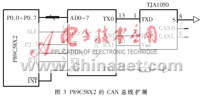
SJA1000 and P89C58X2 are also connected by bus, and the connection method is the same as LM629, and the connection between SJA1000 and TJA1050 is as follows: TX0 of SJA1000 is connected to TXD of TJA1050, RX0 is connected to RXD, RX1 is connected to Vref output, TX1 pull-down resistance of SJA1000 is grounded, TJA1050 The CANL and CANH are the CAN bus output. When multiple nodes are connected, 1 to 2 termination resistors with a resistance of 120Ω need to be added between CANL and CANH, which can effectively prevent the signal reflection generated on the communication bus (see Figure 3). In software design, CAN is operated in PeliCAN, single filter, normal mode and extended frame mode by modifying the register of SJA1000.
2 CAN application layer protocol
In order to allow various distributed modules to work together efficiently, make a regulation on the format and meaning of data transmission, this is the application layer protocol.
2.1 Application layer protocol of CAN bus
Certain protocol support is required between the control systems. This system adopts a master-slave control mode. The master control module serves as the receiver, processor, and driver of the sensor signal; the signal input module serves as the information collector and The filter; and the servo control module and the valve drive module act as the performer (see Figure 4).
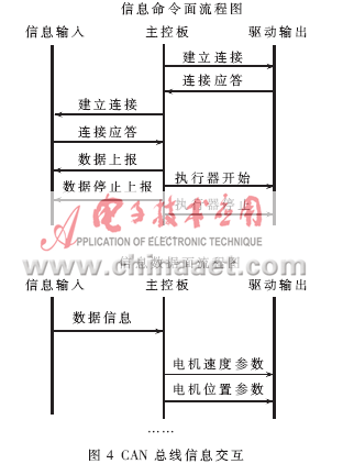
On the information control plane, the main control module should send a "establish connection" request to other control modules, and then start working after receiving the "connection replies" from all the modules. Otherwise, a connection error message will be sent out, indicating that there are no connected modules. The main control module can open and close the link between the main control module and the signal input module through the "data report" command and the "data stop report" command. The "actuator start" command and "actuator stop" command are used to start or stop the drive, which can refer to DC motor or pneumatic valve.
2.2 Data frame structure of CAN bus
CAN accepts a frame up to 8 bytes, this article specifies the application layer protocol, as shown in Table 1.

The source address refers to the initiator of the command; the data / command indicates whether the frame is command plane information or data plane information; the function indicates the role of the frame, such as a "recommended connection" request; the number of data bits indicates the number of data bytes, at most Four bits, this bit is ignored for command frames.
3 Software development platform
According to the requirements of different mechanical systems, designers can choose different combinations of hardware. In order to facilitate software design, the controller uses the CSOS operating system developed by the author. This operating system is based on the time slice rotation algorithm and supports multi-task operation. The data between each task is transmitted through global variables, which occupies less system resources, is easy to learn, and is easy. It is suitable for the requirements of this control system.
3.1 Multi-task operation of the controller
Information acceptance tasks, including signals from external sensors, or command information and data information on the bus, throw the information to obtain useful data (such as the useful information segment in the CAN protocol frame) and throw it to the data channel to provide other task calls.
The algorithm processes the task, gets the information field from the data channel, and throws the result to the data channel after calculation.
Information output task, pack the algorithm task data result and send it to the driver or CAN bus, which is used to drive the controller or put the data packet to the CAN bus.
LCD display task and keyboard input task, these two tasks are respectively responsible for data display and keyboard input.
3.2 Multitask assignment example
Take the software of the main control module as an example to illustrate the above architecture, as shown in Figure 5.
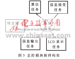
Each task runs independently, puts its own calculation data into the data channel, or obtains the corresponding data from the data channel for calculation. This kind of architecture is clear and flexible.
4 controller application examples
The author applies this control system to the line-finding robot's line-finding control, that is, the robot follows the guide line with a certain width on the ground.
4.1 Hardware selection
According to the control requirements, the signal input module, main control module and servo drive module are needed on the hardware.
4.2 Sensor placement and signal input module
The author uses a photoelectric sensor, using the principle that different colors reflect light differently to distinguish the guide lines on the ground. The layout of the photoelectric sensor is shown in Figure 6.
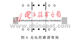
The robot uses 14 photoelectric sensors (digital quantity), black dots indicate 0 on the guide line, and white dots indicate 1 outside the guide line, and through the relationship between the photoelectric sensor spacing and the width of the guide line, only a maximum of 3 are guaranteed The photoelectric sensor is in the guide line, and the current posture of the robot can be known from such a series of logical combinations. The algorithm task in the signal input module filters the collected signals, filters the false signals, and then transmits the data to the information output task, which is packaged and sent to the bus.
4.3 Hunting algorithm and main control module
After the information receiving task of the main control module obtains the above information, it unpacks and throws the relevant data to the data channel, and the algorithm task obtains the data to perform the operation.
It can be seen from Figure 6 that there are 9 states between the 7 photoelectric sensors and the guide line.The upper and lower two states can determine the current pose of the robot, which constitutes a 9 × 9 two-dimensional matrix, and it is easy to know that there are 81 different combinations . The current state of the robot can be obtained through this two-dimensional matrix, using nine states of left polar deviation, left large deviation, left middle deviation, left small deviation, normal, right small deviation, right middle deviation, right large deviation and right polar deviation Indicates that the integer corresponds to -4 to +4.
Give the PID expression of the robot hunt control:

Where ΔVk is the speed difference between the left and right wheels required at the kth moment, that is, the motor speed parameter transmitted on the bus; e represents the difference between the offset state and the normal state, here is the integer corresponding to the state; kp, kI, kD These are proportional, integral and differential constants.
The algorithm task throws ΔVk into the data channel, and the information output task packages it and sends it to the CAN bus.
4.4 Output drive and servo drive module
After the module receives ΔVk, it adopts the “equalization principle†to increase the differential equalization on the left and right wheel motors, namely:

VL and VR are the output speed of the left and right wheels respectively, and Vm is the output of the left and right wheels without deviation.
The algorithm task converts VL and VR into the parameter format conforming to LM629 and sends it to the data channel. After the information output task obtains the data, it directly drives the LM629.
The information flow chart of the entire control system based on CAN bus multi-task architecture is shown in Figure 7.
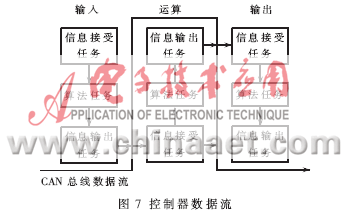
CAN bus can be regarded as transparent under the framework of multi-task operating system, the communication between modules can be simply regarded as the communication between various tasks, and the seamless connection between each module is achieved. When using this controller to design electromechanical systems, the designer's attention only needs to be placed on the algorithm task of each module. This system can well meet the needs of students' technological innovation, facilitate students to construct electromechanical systems or robot controllers, and allow designers to focus more on electromechanical control algorithms.
We adopt the advanced technology imported from Europe, patented technology, specialized software to optimize the design for Dry Type Transformer. The core is made of cold-rolled grain-oriented silicon steel sheet which cut in step-lap by GEORG Germany TBA core cutting lines and laminated by the method of fifth-order step-by-step stacking technology, enabling the no-load performance of the core to improve greatly. The epoxy resin from American HUNTSMAN is adopted for the windings which casted in the vacuum resin casting machine imported from HEDRICH, Germany. The winding material ensures good permeability, no bubbles occur, which leads to minimum partial discharge. The HV and LV winding mate with each other tightly, which ensures solid strength of structure and capability to withstand short circuit and vibration. Under normal service condition, the service life of dry type transformer is 30 years. No crack will form on the surface of transformer winding due to temperature variation as long as the transformer runs under normal service condition.
Dry Type Transformer
Dry Type Transformer,High Quality Special Transformer,1600Kva Dry-Type Transformer,800Kva Dry-Type Transformer
Hangzhou Qiantang River Electric Group Co., Ltd.(QRE) , https://www.qretransformer.com