Dual power switching applications are widely used in various industries. Let’s take a quick look at how to implement automatic switching using relays and contactors.
Here is another diagram showing the setup:


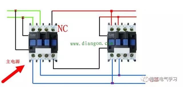
In this configuration, the coil of the backup power supply is connected to the normally closed contact of the main contactor. When the main power is active, the main contactor closes, allowing the main power to be connected to the circuit. If the main power fails, the backup power is activated through the normally closed contact of the main contactor. Once the main power is restored, the backup is automatically disconnected.
Alternatively, you can use a contactor interlock system, but it can be more complex. One challenge is what happens if both the main and backup power supplies are energized at the same time. To avoid this, the system must follow a strict sequence. While there are multiple ways to achieve this, the method is not unique.
Another example of such a setup is shown below:
Here are the diagrams:


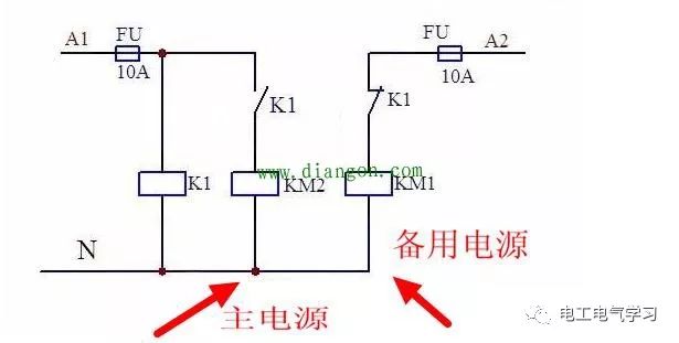
In this case, the main power contactor coil is connected to the normally open contact of a relay, while the backup power contactor coil is connected to the normally closed contact of the same relay. When the main line is powered, the relay activates, closing the normally open contact and opening the normally closed one. This ensures that only the main power is active. When the main power fails, the relay de-energizes, causing the normally open contact to open and the normally closed contact to close, which then activates the backup power.
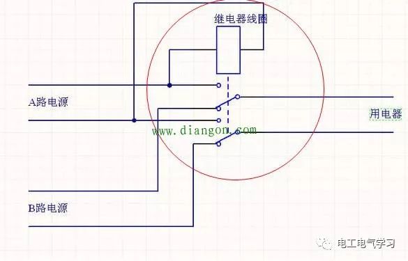
Another variation uses a double-throw relay. When powered, both sets of contacts close, and when power is removed, they return to their original state. This allows for a more compact design. For instance, if the A channel is a 220V AC power source, the relay coil should also be rated for 220V AC.
However, contactors and relays have a certain time delay during switching, which may cause a brief interruption for high-power devices. For example, a light bulb might flicker or a motor might momentarily stop. In self-locking circuits, this could lead to the device being completely turned off.
Here's a manual version of the setup:
And the corresponding diagrams:


This setup requires manual operation and can be more expensive. However, if you have a friend with technical skills, you can build your own control circuit.
It's important to note that power conversion always involves a short time gap, so a seamless switch is not possible. This type of system is mainly used in critical areas like uninterruptible power supply (UPS) systems, where it automatically switches the load to a backup power source when the main power fails.
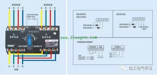
There are different types of dual power switches:
(1) **STS (Static Transfer Switch)**: Also known as a static switch, it automatically transfers power between two sources. It operates in less than 8 milliseconds, making it ideal for sensitive IT equipment. It requires synchronization between the two power sources and is typically used in UPS-UPS, UPS-generator, and similar configurations.
(2) **ATS (Automatic Transfer Switch)**: This mechanical switch is commonly used in emergency power systems. It has a longer switching time (over 100 milliseconds), which may cause a momentary power loss. It is suitable for lighting and motor loads.
And here are the diagrams:


Dual power switches are classified into PC-level and CB-level types. The PC-level is a mechanical switch with an electronic lock, offering higher reliability. The CB-level includes circuit breakers for overload and short-circuit protection.
When choosing a dual power switch, consider the following factors:
1. **Reliability**: PC-level switches are generally more reliable due to their mechanical-electronic locking mechanism, making them suitable for high-safety environments.
2. **Switching Time**: PC-level switches are slower but more durable, while CB-level switches are faster and often used in residential settings.
3. **Short-Circuit Protection**: PC-level switches do not include built-in short-circuit protection, so additional circuit breakers may be needed based on the system requirements.
4. **Isolating Switches**: Adding isolating switches increases cost and complexity, so they are typically only used where necessary, especially in industrial systems.
220V To 110V Transformer
220V To 110V Transformer,220 To 110 Converter,220 To 110 Voltage Converter,110V Transformer
zhejiang ttn electric co.,ltd , https://www.ttnpower.com