Detailed Baud Rate Generator Programming / Calculation / Baud Rate Selection
What is the baud rate generator?
In the information transmission channel, the signal unit carrying the data information is called a symbol, and the number of symbols transmitted through the channel per second is called a symbol transmission rate, which is simply referred to as a baud rate. It is expressed in terms of the number of carrier modulation state changes per unit time. The baud rate generator is used to convert the required baud rate clk from the input clock. Often used in microcontrollers. The amount of information transmitted through the channel per second is called the bit transmission rate, or simply the bit rate. The bit rate represents the transmission rate of valid data. The relationship between the baud rate and the bit rate is the bit number = baud rate X the number of binary bits corresponding to a single modulation state. The baud rate is an indicator of the transmission channel bandwidth.
Baud rate generator baud rate programming
A complete baud rate generator implemented by verilog:
Module baud_gen(
Clk_50MHz, rst_p, bclk
);
Input clk_50MHz; /* input system clock, 50MHz*/
Input rst_p; /* reset pulse, active high*/
/* Multiplier value 16 times 9600 baud rate, ie 9600*16=153600, the actual output signal frequency of the baud rate generator is 153.6kbit/s */
Output bclk; // Output signal: UART (serial port) baud rate generator output clock pulse, frequency: 153.60kbps
/ / 1536000 pulses per second, * baud rate generator output pulse bclk, note: In addition to the main frequency division,
/ / Also determines the duty cycle of this signal, in this case the output signal duty cycle is 1:325
Reg bclk; //register data type bclk
Reg [8:0] cnt; / / register data type cnt, 9 bits, UART used to record the number of received main frequency pulses,
/ / Note that when modifying the output baud rate value, if the duty cycle is less than 1:511, you need to increase the number of bits in the variable
/ / The following statement uses the synchronization counter to complete the clock division,
Always @(posedge clk_50MHz) begin /* Whenever the signal clk_50MHz changes level, execute the following statement */
If(rst_p) begin /* If the reset pulse signal is high, execute the following statement */
Cnt "= 0; // Make a non-blocking reset assignment to the main frequency signal counter cnt, assigning a value of logic 0. Thereafter, whenever the clock signal comes, it changes.
Bclk <<= 0; /* The register variable bclk is assigned a logic 0 to reset the pulse signal to a low level, starting with a low level*/
End
Else begin
/* 50MHz divided by 153600 (UART actual frequency) is equal to 325.5 ie 50_000_000 /153600 = 325.5 (baud rate divisor) */
If(cnt 324) begin /* If the value of cnt is greater than 324, the number of cnt count pulses is equal to 325 (0-324 pulses)*/
Cnt <<= 0; /* 50MHz main frequency signal counter cnt value, reset by non-blocking mode*/
Bclk "= 1; / * serial port baud rate clock pulse signal bclk is assigned a logic 1, which causes the pulse signal to transition to a high level period * /
End
Else begin
Cnt "= cnt + 1; /* 50MHz main frequency signal counter cnt value is incremented by non-blocking mode (plus 1) */
Bclk <<= 0; //Baud rate generator clock signal bclk is assigned '0' by non-blocking mode.
/ / Make the pulse signal jump to a low period * /
End
End
End
Endmodule
Baud rate calculation
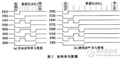
In serial communication, the transmitting and receiving parties have certain agreement on the data rate of sending or receiving. We can define four working modes by programming the MCS-51 serial port through software. Among them, the baud rate of mode 0 and mode 2 is fixed, and the baud rate of mode 1 and mode 3 is variable, which is determined by the overflow rate of timer T1.
The four modes of operation of the serial port correspond to three baud rates. Since the source of the shift clock of the input is different, the formula for calculating the baud rate of each mode is also different.
First, the mode 0 baud rate
In mode 0, the shift clock pulse is given by 56 (ie, the sixth state cycle, the twelfth beat), that is, one shift clock is generated per machine cycle, and one bit of data is transmitted or received. Therefore, the baud rate is one-twelfth of the oscillation frequency and is not affected by the SMOD in the PCON register, ie: Mode 0 baud rate = fosc/12
Second, the mode b and the mode 3 baud rate
The shift clock pulse of mode 1 and mode 3 is determined by the overflow rate of timer T1. Therefore, the baud rate is determined by the overflow rate of timer T1 and the SMOD value, that is, the baud rate of mode 1 and mode 3 = 2SMOD/ 32·T1 overflow rate
Among them, the overflow rate depends on the count rate and the preset value of the timer. The count rate is related to the state of the C/T in the TMOD register. When C/T = 0, the count rate = fosc/2; when C/T = 1, the count rate depends on the external input clock frequency.
When the timer T1 is used as the baud rate generator, it is usually selected to automatically load the initial value mode (working mode 2). In the working mode 2, TLl is used for counting, and the initial value of the automatic loading is placed in THl. When the initial value of the design number is x, the timer T1 will generate an overflow every "256 x x" machine cycles. In order to avoid interruption due to overflow, the T1 interrupt should be disabled at this time.
Baud rate generator baud rate selection
In serial communication, the data transfer rate (baud rate) of both senders and receivers must be agreed upon. In the four modes of operation of the 8051 serial port, the baud rates of modes 0 and 2 are fixed, while the baud rates of modes 1 and 3 are variable, controlled by the overflow rate of timer T1.
Mode 0
The baud rate of mode 0 is fixed at 1/12 of the main oscillation frequency.
Mode 2
The baud rate of mode 2 is determined by the selection bit SMOD in PCON, which can be expressed by:
The SMOD power of baud rate = 2 is divided by 64 and multiplied by a fosc, that is, when SMOD = 1, the baud rate is 1/32 fosc, and when SMOD = 0, the baud rate is 1/64 fosc.
Mode 1 and Mode 3
Timer T1 acts as a baud rate generator with the following formula:
T1 overflow rate = T1 count rate / number of cycles required to generate an overflow
The T1 count rate depends on whether it operates in the timer state or the counter state. When operating in the timer state, the T1 count rate is fosc/12; when operating in the counter state, the T1 count rate is the external input frequency, which should be less than fosc/24. The period required to generate an overflow is related to the operation mode of the timer T1 and the preset value of T1.
Timer T1 operates in mode 0: Number of cycles required for overflow = 8192-x Timer T1 operates in mode 1: Number of cycles required for overflow = 65536-x
Timer T1 works in mode 2: Number of cycles required for overflow = 256-x
Since mode 2 is an 8-bit timer/counter mode that automatically reloads the initial value, it is most appropriate to use it as a baud rate generator.
When the clock frequency is 11.0592MHZ, it is easy to obtain the standard baud rate, so many single-chip systems use this crystal that looks "weird" is the reason.
The following table lists the common baud rate and initial value for Timer 2 operation in Mode 2.
Commonly used baud rate Fosc (MHZ) SMOD TH1 initial value 19200 11.0592 1 FDH 9600 11.0592 0 FDH 4800 11.0592 0 FAH 2400 11.0592 0 F4H 1200 11.0592 0 E8H
E.g. 9600 11.0592 0 FDH
T1 overflow rate = T1 count rate / number of cycles required to generate an overflow
Number of cycles required to generate an overflow = 256-FD(253)=3 SMOD=0 11059200/12*3 *1/32=9600
50W Medical Power Supply,Battery Backup For Medical Equipment,Medical Ac Adapter,Isolated Power Supply For Hospital
Shenzhen Longxc Power Supply Co., Ltd , https://www.longxcpower.com