Automotive EMC simulation process
The rapid development of the automotive industry and the fierce competition in the automotive market have greatly promoted the wide application of various electrical, electronic and information equipment in automobiles. For today's automotive industry, the degree of application of electronic technology has become an important indicator for improving the technical level of automobiles. one. Electronic equipment is widely used in automotive engine control systems, automatic transmission systems, braking systems, regulating systems, and driving systems, and plays a decisive role in the safety, reliability, and comfort of automobiles. As the number and types of automotive electrical equipment continue to increase and the operating frequency continues to increase, the electromagnetic environment within automobiles is becoming increasingly complex. At the same time, electronic devices and devices on automobiles, especially semiconductor logic devices, are very sensitive to electromagnetic interference, and the internal electronic devices of the car often interfere with each other. When electromagnetic interference occurs, the function of the sensitive electronic device that is disturbed is degraded, and the function is invalid, which seriously affects the safe driving of the car.
This article refers to the address: http://
1 Automotive Electromagnetic Compatibility System
According to the life cycle of product development, the complete automotive EMC system can be summarized into four steps: design → simulation → test → rectification. The good electromagnetic compatibility of a car comes from a good system design. The earlier the electromagnetic compatibility problem is considered, the more measures can be taken to solve the problem, and the corresponding cost is lower. As shown in Figure 1.
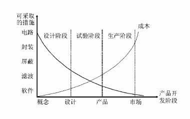
Figure 1 Relationship between EMC design cost and available technical means at various stages of the development process
The electromagnetic compatibility design of a car must first propose the electromagnetic compatibility index of the complete vehicle, system and components according to the safety, performance, function and target market regulations of the vehicle; secondly, the electromagnetic compatibility control plan and test plan should be formulated; According to experience, it is also required to design the electrical structure of the system and the vehicle level. The electrical design of modern cars is shown in Figure 2.
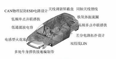
Figure 2 Electromagnetic compatibility measures taken by the car
However, automotive electromagnetic compatibility design has high requirements for electromagnetic theory. Compared with foreign advanced vehicle companies, domestic vehicle manufacturers still have considerable gaps in this respect, which is still in the preliminary accumulation stage of exploration and experience.
For OEMs, EMC testing is divided into two levels: parts and vehicle levels. At different stages of the new product development process, component suppliers are required to perform component testing according to the OEM standard. After the test is passed, it can be used for loading and performing electromagnetic compatibility testing of the vehicle. The test of the whole vehicle is divided into two types: diagnostic test and certification test. The diagnostic test is generally carried out for the engineering prototype. The main purpose is to find the interference source and the susceptible area, and provide the design basis for the suppression of the interference source and the protection of the susceptible area. It is also the direct source of the parameters and input data required for the simulation. . The certification test is based on the electromagnetic compatibility standard to make a final judgment on whether the vehicle meets the electromagnetic compatibility requirements. Electromagnetic compatibility standards include national, international and corporate standards.
Automotive EMC simulation is a method of combining problems with computer simulation to analyze problems. Simulating before electromagnetic compatibility testing can identify electromagnetic compatibility problems early in the design process, reducing or avoiding technical or cost barriers caused by later solving electromagnetic compatibility problems. At present, the research on electromagnetic compatibility simulation of domestic automakers is still very few, mainly because: (1) There are few domestically designed models, mostly direct introduction, lack of accumulation of simulation data; (2) Design with electromagnetic compatibility In the same way, electromagnetic simulation has high requirements on the theoretical basis of electromagnetics. Domestic research in this area started late; (3) There are many factors affecting electromagnetic compatibility of automobiles, and any simplification of the model in the simulation process will lead to actual The simulation results are far from the situation; (4) The structure of the automobile is complex, and there are both electric and small structures, which require high efficiency for modeling techniques and algorithms.
2 Automotive electromagnetic compatibility simulation process and method
2.1 Simulation theory
The research content of electromagnetic compatibility simulation prediction is mainly to establish three elements of electromagnetic compatibility: electromagnetic interference source, coupling path and mathematical model of sensitive equipment, and use appropriate numerical calculation methods to solve these models to evaluate whether the sensitive equipment of the system meets the predetermined electromagnetic Interference margin requirements.
2.2 Simulation process and modeling method
The complete electromagnetic simulation process is shown in the figure
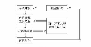
Figure 3 Electromagnetic compatibility simulation process
Establishing the correct simulation model is the most important step in the prediction of automotive electromagnetic compatibility simulation. The matching degree between the established model and the actual prototype will directly determine the accuracy and practicability of the simulation results. And modeling often takes up more than 70% of the entire simulation process.
Modeling should also be targeted for different types of automotive electromagnetic compatibility issues. The analysis of the interference of the external radiation source to the body harness is not the same. But no matter what kind of model, the core is to first identify potential sources of interference, sensitive devices and coupling paths, and then model these three elements one by one.
(1) Interference sources: Most of the current simulation software provides various types of excitation sources---point sources, plane waves, Gaussian waves, current sources, pulses, etc. Simulation of ideal models can be directly adopted as needed. For the actual vehicle condition simulation, the oscilloscope can be used to measure the voltage/current waveform on the interference source connection wire to establish the time domain waveform of the interference source; or the near field probe can be used to measure the electric field distribution near the interference source, and then used as the simulation calculation stimulus. source.
(2) Coupling path: mainly modeling the car body and wiring harness. The accuracy of the division of the electromagnetic surface mesh is determined according to the frequency range of the simulation. The higher the calculation frequency, the finer the meshing requirements. At the same time, the electromagnetic grid of the vehicle body near the interference source and the coupling path should also appropriately improve the division accuracy. Wire harness modeling is generally based on transmission line theory to build a circuit model. The accuracy requirements of automotive structural parameters that have little effect on electrical signals are not high, and structures that have little effect on the results can be ignored.
(3) Sensitive equipment: The modeling of sensitive equipment is mainly to judge whether it interferes. The criterion compares the electromagnetic compatibility threshold of the sensitive device with the magnitude of the electromagnetic interference coupled through the coupling path. For conducted interference, it is possible to judge whether interference occurs by analyzing parameters such as voltage/current peak value, duration, period, etc. of the sensitive device; for radiation interference, it is possible to judge whether interference occurs by the frequency domain distribution of the field strength at the sensitive device.
After the model is established, the simulation is performed using a simple example that is easy to obtain measurement results, and the simulation results are compared with the measurement results, and the model is repeatedly modified according to the comparison result to enhance the matching degree of the model.
3 Electromagnetic Compatibility Simulation Software Introduction
3.1 Numerical calculation method
The core of simulation software is its numerical calculation method. These methods can be divided according to different calculation sizes, time domain and frequency domain, integral and differential classification criteria.
Different calculation methods have their own limitations and limitations: the time domain finite difference method is suitable for calculating broadband problems and can deal with complex non-uniform media, but the meshing of small structures requires high precision, so the memory requirements are extremely high. The finite element method meshing is flexible and easy to handle the problems of multiple media and complex structures, but the external boundary conditions of the open domain are difficult to determine; the moment method allows the mesh of arbitrary shapes to be suitable for the medium because of the nature of its numerical integration. The surface is simulated, but it is difficult to deal with the multi-layer media problem; the transmission line matrix method is easy to handle transiently changing fields, but the frequency response characteristics require a lot of recalculation to obtain.
3.2 Introduction to Automotive Electromagnetic Compatibility Mainstream Simulation Software
There are many softwares for calculating electromagnetic fields and electromagnetic compatibility problems on the market. Most of these softwares use one or several numerical calculation methods. Due to the pertinence of the algorithm, there is no software that can solve all electromagnetic field problems.
For the particularity of automotive electromagnetic compatibility applications, the simulation software needs to have the following capabilities: to calculate the full 3-dimensional electromagnetic problem; to solve various types of antennas covering the AM to GPS band (whip antenna, windshield glass antenna, GPS antenna, etc.); transmission line method Calculate various types of wiring harnesses, including crosstalk and signal integrity problems between various cables such as single core, twisted pair, and coaxial; 3D electromagnetic field and transmission line coupling; can consider complex body structure and various types of media; Interference sources; test models conforming to ISO, CISPR standards; circuit simulation analysis; complex load design and editing capabilities.
(1) EMCSTudio
Basic situation: EMCStudio was developed by the EMCOS company in Georgia for automotive EMC. The predecessor of EMCOS was the Electromagnetic Research Laboratory of the University of Tbilisi. OEMs currently using EMCStudio include Audi, Volkswagen, Mitsubishi, Nissan, Renault and others. Core algorithm: moment method, transmission line method, equivalent source method, circuit analysis, physical optics. Its greatest advantage is the combination of the method of moments, transmission line method and circuit analysis. The electromagnetic interference calculation including the vehicle body and the complex wiring harness can be completed in one operation.
Calculation module: Model the test requirements of automotive EMC in full accordance with ISO and CISPR. With multiple calculation modules such as anti-interference analysis, disturbance analysis, crosstalk analysis, high current injection (BCI), virtual platform and circuit analysis, it is highly targeted.
Pre-processing: Convenient geometric modeling, support for a variety of CAD data format import. For CAE analysis, the meshing of the model tends to occupy more than 50% of the pre-processing, and the quality of the meshing is directly related to the accuracy of the calculation results. EMCStudio's embedded REMESH tool has powerful electromagnetic meshing and editing capabilities for easy modeling.
Post-processing: The calculation results are relatively simple to display, but the interface is completely open to the user. Users can edit the data to form various types of reports.
Diagnostic function: Provides diagnostic debugging function similar to computer programming language, which accurately and intuitively informs the user of the specific location of the error, which is convenient for error correction.
Harness tool: For automotive EMC, the modeling and analysis of wire harnesses plays an extremely important role. In addition to supporting the import of mainstream harness data formats (KBL, XML, SteP), EMCStudio can also create and edit harness data on its own.
(2) FEKO+CableMod
Core algorithm: FEKO has a moment method, a fast multi-level sub-method, a physical optics method, and a consistent diffraction method. CableMod calculates the harness using transmission line and circuit analysis. The advantage of FEKO is that its fast multi-level sub-method can greatly reduce the memory requirements, thus greatly reducing the calculation time and calculating the size of the large size. At the same time, FEKO has an automatic optimization calculation module, which can easily optimize and adjust the model parameters to provide reference for EMC design. However, since it is two separate softwares, it is necessary to carry out step by step when calculating the electromagnetic interference problem of the complicated wiring harness in the vehicle body. Take the external electromagnetic field to interfere with the wiring harness inside the body as an example: first use FEKO
The body without the wire harness is calculated, the surface current is obtained and exported as RSD data, and the RSD data is used as an excitation source to be introduced into CableMod to calculate its interference to the wire harness.
Pre-processing: powerful geometric modeling capabilities, user-friendly modeling tools, support for a variety of CAD data format import. But without the editing capabilities of complex meshes, other CAD meshing tools are needed.
Post-processing: A rich GUI graphics processing tool that allows users to edit calculation results.
Diagnostic function: It is cumbersome to use the tab function in EDITFEKO to diagnose the model error.
Harness tool: The CableMod software itself is a tool specifically designed for wire harness modeling and calculations to meet all modeling and calculation needs of automotive wiring harnesses.
Compared with FEKO+CableMod, EMCStudio is highly targeted and fully conforms to the modeling and calculation of automotive electromagnetic environment. Its hybrid algorithm facilitates the user's calculation process. The latter's fast multi-level sub-algorithm greatly improves computational efficiency, making it possible to calculate high-frequency and large-size automotive EMC problems.
4 Conclusion
It is expensive to solve the problem of electromagnetic compatibility of automobiles by testing alone. The electromagnetic simulation technology can be used to extend the process of discovering and solving electromagnetic compatibility problems of automobiles. At present, the two mainstream simulation softwares on the market have their own advantages, and users need to choose according to actual needs. At the same time, it should be pointed out that because the modeling does not completely replicate the actual electromagnetic environment of the car, the simulation results will have some errors, and the modeling techniques and numerical calculation methods still need to be developed.
Magic Led Ball, we also called it Led Magic Ball Light, we hang the ball on the tree, in the street, in the air to make it in a wide view. also we can put the ball on the floor or desk as well. The led magic ball light mostly for stage lighting, disco llight ball, park decoration, celebration and so on.
The Magic LED Ball can do dmx rgb Led Ball or warm white led ball, golden led ball. The standard size of the magic color led ball is 200mm diameter, 250mm diameter, 350mm diameter, 500mm diameter. and the even bigger led ball which can realize a customized design.
Photo show of Magic LED Ball:


Magic LED Ball
Magic Led Ball,Magic Led Hanging Ball,Led Magic Ball Light,Disco Light Ball
Shenzhen Iseeled Technology Co., Ltd. , https://www.iseeledlight.com