Application of Intelligent IGBT in Automobile Ignition System
To generate sparks, the devices you need include power supplies, batteries, transformers (ie, ignition coils), and switches that control the primary current of the transformer. The electronics textbook tells us that V=Ldi/dt. Therefore, if the current in the primary winding of the coil changes instantaneously (i.e., the di/dt value is large), a high voltage will be generated on the primary winding. If the turns ratio of the ignition coil is N, the primary side voltage can be amplified according to the winding turns ratio. The result is a voltage of 10kV to 20kV across the secondary, spanning the spark plug gap. Once the voltage exceeds the dielectric constant of the air surrounding the gap, the gap will be broken to form a spark. The spark ignites a mixture of fuel and air to produce the energy needed to operate the engine (Figure 1).
This article refers to the address: http://
In addition to diesel engines, all internal combustion engines have a basic circuit (automobile ignition system). Switching elements for ignition coil charging have undergone great evolution: from a single mechanical switch, multiple breaker contacts in a distributor, to high-voltage Darlington bipolar installed in a distributor or in a separate electronic control module The transistor is connected to an insulated gate bipolar transistor (IGBT) mounted directly on the ignition coil of the spark plug, and finally the smart IGBT directly mounted in the ignition coil of the spark plug.
Many years ago, IGBTs have become switches in ignition applications. Figure 2 shows a cross-sectional view of the IGBT. Compared with other technologies, IGBT has the following important advantages:
The saturation pressure at high current is reduced;
Easy to build a circuit that can handle high voltage coils (400~600V);
Simplified MOS drive capability;
Can withstand high energy consumption (within SCIS rated range) when the coil is working abnormally.
The schematic diagram of the ignition IGBT shown in Figure 2 includes several additional important elements. The collector-to-gate avalanche diode stack establishes a "on" voltage. When the collector is forced to rise to this voltage by a flyback or spike from the coil, the IGBT will conduct, and the IGBT will consume its active area. The remaining energy accumulated in the coil (rather than using it to create a spark). With this avalanche "clamp" circuit, the IGBT can limit the clamping voltage to a much lower breakdown voltage than the N-type epitaxial doped/P-substrate (N epi/P base) semiconductor to ensure its safety. run. This significantly increases the ability of the ignition IGBT to withstand the energy of the self-clamping inductive switch (SCIS). This capacity is a rated indicator, that is, the energy absorbed by the IGBT each time the energy in the ignition coil is released as a spark. By limiting the voltage on the primary coil, the ignition coil itself is also over-voltage protected.
The latest generation of IGBTs has been able to significantly reduce the die area in IGBTs while still maintaining excellent SCIS capability. This advancement is spawning multi-die smart IGBT products. These smart products combine high-performance BCD IC technology with high-performance power discrete component IGBTs. The demand for the intelligent IGBT coil drive circuit is that the development direction of the power switch is changed from an external engine control module to a component directly in the ignition coil on the spark plug in the engine. When the ignition coil is located on the spark plug, this structure is called "coil on plug"; when the coil drive circuit is included in the coil, this structure is called "switch on coil".
The "switch on coil" structure offers significant advantages in terms of system performance, reliability and cost. Some of its advantages are as follows:
No high voltage spark plug wire is required;
No heat is generated in the engine control module;
Save space in the engine control module;
The actual spark generation can be monitored to improve engine control.
The last performance advantage has spurred demand for smart IGBTs. As a result, automotive ignition switch functions are evolving into smart devices that monitor spark conditions, take current limiting measures to protect the coil, and pass the engine's ignition status to the engine control system.
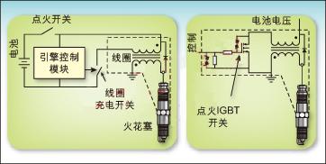
Figure 1: Schematic diagram of the car ignition system
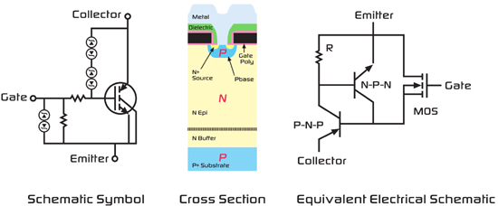
Figure 2: IGBT profile
Ideal smart IGBT function in "switch on coil" application
1. Signal interface of the engine control module.
There are many problems with the "on-coil switch" smart IGBT driven by the engine control module. The electrical environment noise under the hood is very disturbing. The signal interface of the engine control module not only needs to cope with these noises, but also solves the potential problem of several meters of connection between the engine control module and the coil position. Electrical noise can come from EMI radiated signal noise or magnetic induced noise caused by large currents in adjacent lines.
In addition to the above noise problems, there is a voltage difference of several volts between the actual ground reference point of the engine control module and the ground point at which the coil or engine is located. Therefore, the defined interface between the engine control module and the intelligent ignition coil drive circuit must be able to cope with these problems.
2. Protect the ignition coil.
The input signal in Figure 3 commands the IGBT to begin charging the ignition coil. Under normal conditions, the current will reach 7~10A when the coil stops charging and releases sparks. However, when the engine is at a low speed, especially during an emergency deceleration or engine control time, if the input is not cut, the IGBT will cause the coil charging current to exceed the rated value, which may cause damage to the coil winding.
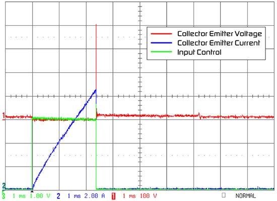
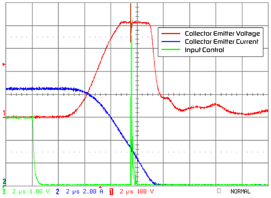
Figure 3: Typical ignition waveform
Smart IGBTs have been designed with several circuits to prevent ignition coils from being damaged in this situation.
The first is a current limiting circuit that directly measures the IGBT collector current with a sense resistor or with a current sense IGBT. Figure 4 shows these two circuits.
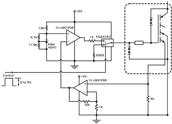
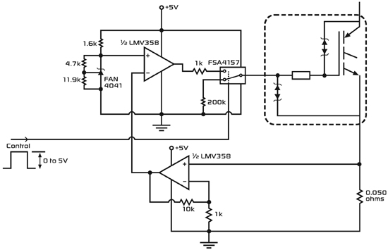
Figure 4: Current limiting circuit
The advantage of direct measurement is that the coil current can be measured very accurately, but at a higher cost. The sense resistor connected in series with the emitter lead through the 7~10A coil charging current will significantly increase the total voltage drop of the power switch, and will generate additional energy dissipation and heat, which will cause trouble in the design. Another negative effect is that the resistance in series with the IGBT reduces the charging speed of the coil, which affects the timing of the system.
The current sensing IGBT is designed in such a way that it splits a small portion of the total current into a current monitoring circuit for detecting the total current of the IGBT collector. This type of IGBT eliminates the two problems of direct measurement techniques because no additional resistors are connected in series to the large current path of the IGBT. However, since this technique is no longer a direct measurement of the emitter current, some additional system errors must be considered in the design, such as the ratio of the divided current sensing to fluctuations with temperature or total current. Some of the current sensing IGBTs are connected in parallel with their main IGBT sections, but are connected to separate emitter pads. Therefore, a portion of the total collector current will flow through this sensing portion (or control portion) of the IGBT. The ratio of the current flowing through the control portion of the total collector current depends mainly on the ratio of the shunt unit of the control region to the remaining active region unit in the IGBT. However, if there is any difference in the operating conditions between the control section and the main active area, this current ratio will be affected, which will affect the accuracy of current sensing. Of particular concern is how to keep the body portion of the IGBT and the emitter of the control portion at the same potential. Any dropout will directly change the gate to emitter voltage of that section.
Once the IGBT limits the coil charging current, the overcurrent problem of the coil is resolved. However, at this time, the IGBT itself is still in a state in which energy dissipation is extremely high, and it is impossible to be in such a condition for a long time without damaging the IGBT. Under current limiting conditions, the power in the IGBT will climb to 60W to 100W. When installed in the ignition coil, the thermal resistance of the IGBT to the surrounding can be as high as 60~70oC/W, because there is no good heat dissipation channel in the coil. Therefore, the junction temperature Tj = Ta + Pd × Rth (ja), under these conditions, the junction temperature of any semiconductor device will quickly exceed the acceptable junction temperature limit.
One solution to the above problem is to add a "Maximum Dwell" circuit to the smart IGBT. This circuit provides a suspend function to turn off the IGBT after the coil has been charged for a certain period of time to prevent the IGBT from overheating.
Similar to the current limiting circuit, the maximum pause circuit also protects the IGBT, but it has a negative effect. It is possible to ignite without distinction when the maximum pause circuit takeover time exceeds a preset limit. Typically, the maximum pause circuit is not controlled by the engine management system, and its operation depends on when the IGBT begins to charge the ignition coil. This makes it possible to ignite at an improper piston position and damage the engine.
Smart IGBTs solve this problem by adding a function called "soft shutdown." The soft-shutdown circuit takes effect when the maximum pause time reaches the set value. It controls the IGBT to slow its current, rather than interrupting it immediately. Since the collector current is always ramped down, the voltage generated in the coil can be kept low, preventing ignition events from occurring outside of the engine management system settings.
Smart IGBTs also monitor the secondary voltage of the ignition coil for information on spark quality. The secondary coil voltage is reflected to the primary winding by the coil's winding ratio. This information can be captured and transmitted back to the engine management system to optimize engine performance to increase power or reduce emissions.
These suggestions are only a small part of the various functions that the ignition switch brings when placed in the ignition coil. The specific ignition functions and characteristics used by different engine control manufacturers vary widely; however, the overall trend reflected in many emerging system developments is the use of “coil-on-switch†technology, which has advantages in both cost and performance.
These added ignition functions can be optimally combined with IGBTs by using multiple die packaging techniques. The automotive environment (especially the ignition environment) usually has a high temperature and great noise interference. By physically isolating the IGBT from the control circuit, it is possible to improve the noise immunity of each device and reduce temperature-induced problems. The design and process focus of the IGBT can be focused on some of the key parameters of the IGBT, such as SCIS and Vce(on), while the control IC can be optimized for high-performance analog functions.
Figure 5 shows several smart IGBTs under development, all using multi-die package technology. These products use the latest EcoSpark IGBT technology, the industry's highest level of SCIS capability per unit area, and its Vce(on) is extremely low. Using a high-performance analog BICMOS control die, the entire smart ignition coil driver circuit can be incorporated into a single package.
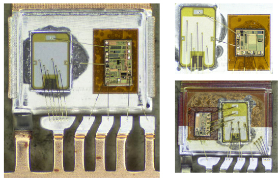
Figure 5: Multi-die smart ignition design
The control die and IGBT are combined in a multi-pin TO-220 or TO-263 package. The IGBT is soldered to the header of the package to minimize the resistance and thermal resistance between the IGBT and the package. The control die is bonded to the same header with an insulating polyimide material to isolate it from the high voltage collector of the IGBT.
Another alternative configuration is to mount the IGBT and control die and other required external components in a small module that can be placed in the ignition coil. Figure 6 shows several examples of this configuration.
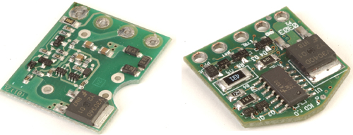
Figure 6: Intelligent ignition system developed on printed circuit boards
Regardless of the configuration, it is clear that the ignition power switch and the control/monitoring intelligence are gradually incorporated into the ignition coil. There are many difficulties in developing these new intelligent ignition devices:
High-voltage, high-current power switches and low-power analog control circuits need to be close together;
High working temperature
There may be various transient phenomena that damage the battery;
More high performance analog functions;
Small size;
The heat dissipation conditions are poor, but the power dissipation is large.
If the mechanical contact technology installed in the automotive distributor is counted, the ignition system has gone through a long period of development. Today, these mechanical contacts and distributors have been abdicated. The IGBT switch that controls the current in the coil is more than just a switch, but a control element integrated with the rest of the engine management system. The functions that need to be included in coil switches will become more and more, such as the development of multi-spark systems for improved fuel combustion, and the addition of secondary (spark plug) current monitoring to monitor combustion quality.
The latest ignition IGBTs, mixed-signal ICs and packaging technologies enable the system advantages that are allowed by the "on-coil switching" technology. Therefore, the next time you refuel and speed up, you may not think of the spark that makes the engine work, but the smart ignition IGBT is working hard to bring you to where you want to go.
Washing machines are very common in every family. Banshen washing machines, with high quality, good design and best service. Many products have been sold to over 30 countries. After many years of developing, banshen washing machines are getting better and better.
Our well-equipped facilities and excellent quality control throughout all stages of production enable us to guarantee total customer satisfaction. Besides, we have received CE, CB, RoHS and CCC certifications.
As a result of our high quality products and outstanding customer service, we have gained a global sales network reaching America, Asia, Europe, Africa, the Middle East and other countries and regions.
If you are interested in any of our products or would like to discuss a custom order, please feel free to contact us. We are looking forward to forming successful business relationships with new clients around the world in the near future.
9.5~12kg Twin Tub Washing Machine
12V Dc Washing Machine,Top Loading Washing Machine,Glass Cover Washing Machine,9.5Kg Twin Tub Washing Machine
Ningbo Banshen Electric Appliance Co., Ltd , https://www.banshendq.com