Design of Strapdown Inertial Navigation and Display System Based on Autoface
With the rapid development of science and technology, inertial navigation technology is widely used in the military field, and can accurately guide weapons, aircraft, aircraft and so on. The early inertial navigation system used a mechanical platform and was gradually replaced by the Strapdown Inertial Navigation System (SINS). Modern high-tech warfare requires the weapon system to be responsive, simple to operate, and highly reliable. It has spawned the birth of a touch-screen weapon control system, such as the US military's single-touch GPS Navigator and the German's touch-type gun aiming system. China's Strapdown Inertial Navigation System started late, but due to the maturity of domestic related devices (such as laser gyro, accelerometer) manufacturing technology, China's Strapdown inertial navigation technology has also developed rapidly and achieved certain achievements. In this paper, the actual control of the laser gyro strapdown inertial navigation system is designed in this paper. The display and control part of the laser gyro strapdown inertial navigation system is designed. The display adopts VT5057L monochrome touch screen.
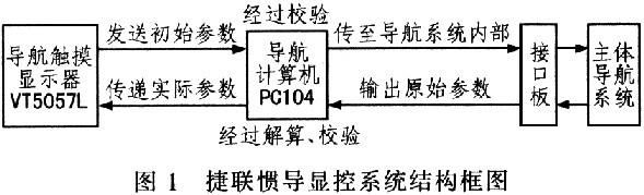
1 Strapdown Inertial Navigation and Control System Structure The Strapdown Inertial Navigation and Control System consists of a navigation touch display and a navigation data processing computer. The navigation touch display is one of the important components of the entire navigation system. It inputs commands to the entire navigation system to control the operation of the entire navigation system. At the same time, it receives the actual navigation parameters after the solution and displays them. Based on these parameters, it is determined whether the entire navigation system is The operation is normal, therefore, the display control system is an important window for the operator to understand the navigation system. The INS system uses the PC104 as a navigation data processing computer. After receiving the initial parameters, it performs verification, and then sends the initial parameters to the main navigation system. At the same time, the original parameters transmitted by the main navigation system are solved to obtain the final navigation. The parameters are passed to the navigation touch display. The software part is written in Micmsoft Visual C++ for compatibility with Win98/2000/XP systems. The navigation touch display and the navigation data processing computer use the RS-232 serial port to realize two-way communication, and the baud rate is 115200. The block diagram of the entire display control system is shown in Figure 1.
This article refers to the address: http://
2 Strapdown inertial navigation display control system design
2.1 Hardware Circuit Design The navigation touch display consists of a VT5057L monochrome touch screen and a 24 V DC current source. The VT5057L provides an RS-232 serial port for connection to the PC104. The receiving and sending of the VT5057L touch screen is for 4-byte 32-bit floating point numbers. The touch screen has two display modes: 1) display the required data after filling the buffer; 2) do not have to fill the buffer completely. As long as the corresponding address has data, it will be displayed; due to the real-time communication, the latter is used here.
The navigation data processing computer consists of an embedded PC104 module and an interface board. The PC104 module provides an ISA bus. The interface board completes the conversion of the laser gyro and accelerometer signals, and transmits data between the bus and the PC104 module through this bus. The laser gyro outputs two square wave signals with a phase difference of 90°, and the accelerometer outputs a proportional current signal, both of which need phase phase demodulation before they can be used. Here I/F transform is used to convert the current signal of the meter into a pulse signal, and then the 8825 is used to count the pulse signal to obtain a digital signal. In addition, since the execution frequency of the navigation software is high, an 8254 timing is added to the interface board. As an external timer. The system interface board uses HCTL2020 device to complete the above work. The device integrates 4 times frequency decoding circuit, 16-bit counter and filter. The built-in filter can effectively reduce noise. Figure 2 shows the navigation of the strapdown inertial navigation system. Computer block diagram.

The interface board is responsible for connecting with the main navigation system to obtain the original data, and the PC104 module is responsible for receiving the initial parameters transmitted by the touch screen, and after being verified, transmitting to the main navigation system, and the main navigation system transmits the navigation original parameters to the PC 104, then it is The transmitted parameters are solved and transmitted to the VT5057L after error compensation correction. The communication protocol of the two is as follows: serial port, COMl; baud rate, 115200; check digit, NONE; data bit, 8; stop bit, 1.
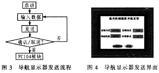
2.2 Navigation Display Software Design The software design of the navigation display is written by Autoface. This software is written in Microsoft Visual C++ mode. Many functional modules are embedded inside. The programmer realizes the corresponding functions by writing macro commands of the module. When the surface module of the screen is touched, the touch screen will automatically execute the corresponding macro command. There is a priority between the macro commands, and the priority is used to control the order in which the commands are executed. The software system of the navigation display is responsible for sending work orders to the main system, and the sending phase process is shown in FIG. Figure 4 is the actual transmission interface of the navigation display.
Since the VT5057L has a large memory and a separate CPU inside, the software can display the data transmitted from the PC 104 in real time with almost no delay. When the actual working environment is bad or the serial port transmission process will generate bit errors, a special field checksum checksum is added in the initial stage, and it is transmitted twice during transmission, and the corresponding verification is performed in the software part of PC104 to ensure The communication is correct. Send the macro command code as follows: 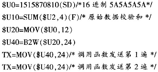
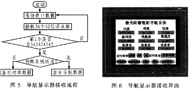
After receiving the work command, the main navigation system will work normally and transmit the original navigation parameters. At this time, the PC 104 receives these navigation parameters and performs parameter calculation. After the solution, the actual parameters are transmitted to the VT5057L, and the display phase of the touch screen is shown in FIG. 5. Shown. Figure 6 is a navigation result actually received by the navigation display. In order to eliminate the link factor and the communication error affecting the transmission between PC104 and VT5-057L, the verification function is added. The display phase macro command code is as follows:


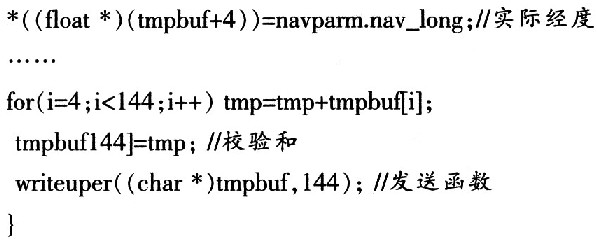
The software of the navigation data processing computer is written in VC++ and debugged under DOS using TC3.1. Because the actual battlefield environment may be volatile, the data traffic of the whole system is very large, and the main navigation system and the display control system may have various problems, which may lead to data transmission errors; in order to prevent such things from happening, inside the navigation computer Also added the data check link, the send function code is as follows: 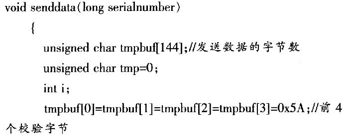
3 Conclusions This paper designs a display and control system based on touch screen and PC104, and gives the frame structure of PC104 calculation module and the writing process of touch screen and navigation computer software. The two communicate through RS-232 serial port, after 4000 hours of uninterrupted testing. The data display is still normal. The display control system is small in size, light in weight and high in reliability, and can be applied to a naval ship inertial navigation system.
Private mould Round IP20 plastic housing series round types,look perfect with the round downlights,CE/ROHS/SAA/ETL/TUV/EMC,Input voltage can be both 110V and 220V,Wattage can be 1-80W, DALI/TRIAC/0-10V/PUSH/WIRELESS dimmable and non dimmable, flicker free,noise free,load free, Perfect dimming curve, PF>0.95,constant current 350mA 700mA 900mA 1200mA,constant voltage 12V 24V 36V, parameters can be customization,OEM/ODM is supported,Same appearances but different sizes, forming a perfect product line,Use for led panel light,led strip light and other indoor led lights
Round LED Driving Lights,LED Driving Lights,Small Round LED Driver,36W Round LED Driver
HAURUI LIGHTING CO.,LTD , http://www.huaruileddriver.com