Dual power switching applications are widely used, and one common method involves using relays and contactors to achieve automatic power transfer. In this setup, the main power supply is usually connected through a contactor, while the backup power is controlled via another contactor or relay.
Using two contactors for power switching allows for a basic automatic transfer system. The standby power contactor’s coil is normally closed when the main contactor is energized, allowing the main power to be active. When the main power fails, the main contactor de-energizes, opening its contacts and closing the standby contactor’s contacts, thereby switching to the backup power. If the main power returns, the system reverts back automatically.
This approach can also be implemented using contactor interlocks, though it may be more complex. It's important to ensure that both power sources do not operate simultaneously, as this could cause issues. The method isn't fixed, and different configurations can be used depending on the application.
Another method involves using one relay with two contactors. The main power contactor is connected to the relay’s normally open contacts, while the backup contactor is connected to the normally closed contacts. When the main power is on, the relay pulls in, closing the main contactor and cutting off the backup. If the main power is lost, the relay de-energizes, allowing the backup contactor to activate.
A double-pole changeover relay can also be used. This type of relay has two sets of contacts that switch between the main and backup power. When the power is on, the relay ensures that the correct circuit is active. If the power is off, the relay switches to the backup. This type of relay is often used in single-phase systems where the coil voltage matches the power supply.
However, contactors and relays have inherent time delays during switching, which can cause momentary interruptions in power. This might result in flickering lights or motor stalling, especially in high-power applications. For such cases, self-locking circuits may be required to prevent unexpected shutdowns.
Manual dual power switches are available but tend to be more expensive. They require human intervention and cannot provide seamless power transfer. There is always a brief interruption during the switch, making them unsuitable for critical applications like uninterruptible power supplies (UPS).
Dual power switches are primarily used in environments where continuous power is essential, such as data centers, hospitals, and industrial facilities. These systems automatically transfer the load to a backup power source when the primary power fails, ensuring uninterrupted operation of critical equipment.
There are several types of dual power switches:
1. **STS (Static Transfer Switch)**: Also known as a static switch, it is an automatic system that transfers power between two sources without mechanical movement. It switches within 8 milliseconds, making it ideal for IT loads. STS requires synchronization between the two power sources to function properly. It is commonly used in UPS-to-UPS, UPS-to-generator, or UPS-to-city power setups.
2. **ATS (Automatic Transfer Switch)**: ATS is a mechanical device used in emergency power systems to switch between the main and backup power sources. Its switching time is typically over 100 milliseconds, which may cause a short power interruption. It is suitable for lighting and motor loads.
Dual power switches are categorized into **PC-grade** and **CB-grade** models. PC-grade switches are mechanical and offer higher reliability, while CB-grade switches include circuit breaker protection. The choice between them depends on factors such as reliability, switching speed, and the need for short-circuit protection.
From a reliability standpoint, PC-grade switches are generally more robust due to their mechanical-electronic locking mechanism. CB-grade switches, on the other hand, rely on electronic control and are faster in switching. However, they are better suited for residential applications where quick response is needed.
It's important to note that PC-grade switches do not inherently provide short-circuit protection. Additional circuit breakers may be required based on the system's needs. Many users mistakenly believe that short-circuit protection is essential for the switch itself, but this is not the case.
In terms of installation, isolating switches can add cost and complexity, so they are often avoided in residential settings. In industrial environments, however, they may be necessary for safety and maintenance purposes.
If you're looking for reliable power management solutions, Guangzhou Mingye Electronic Technology Co., Ltd. offers a wide range of products, including tension controllers, phase sequence protectors, RS485 acquisition modules, PLC driver boards, relay modules, and custom circuit board development. With 17 years of experience in advanced manufacturing, they are a trusted name in the industry. For more information or to place an order, contact Mr. Huang at their factory directly. You can also visit their official website for free consultation and support.
Membrane Switch
What is a membrane switch?
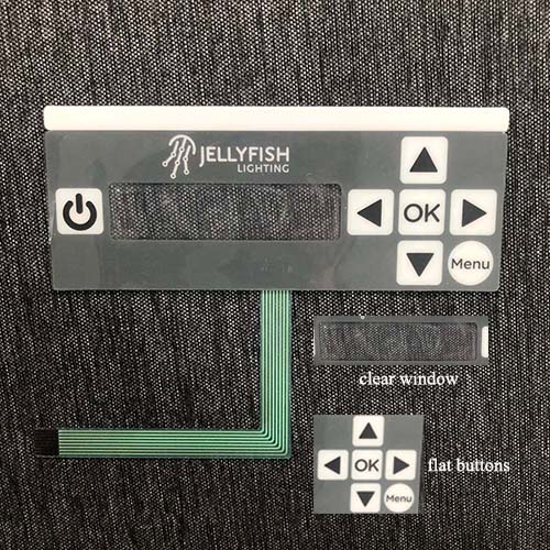
A membrane switch is an operating system integrating key function, indicating element and instrument panel. The membrane switch, also called a membrane keyboard or membrane keypad, is a custom switch assembly that uses pressure to open or close the conducting path in an electrical circuit. The ultimate purpose of a membrane switch is to serve as the interface between man and machine, enabling an operator to communicate with a piece of equipment, instrument, or machinery. Membrane switches are still consistently utilized as user interfaces for a wide range of products from industrial machinery to medical devices to agricultural equipment. Even the most rigorous of industries can count on proven membrane switch technology to provide a reliable, long-lasting human-machine interface.

How about the construction of a membrane switch?
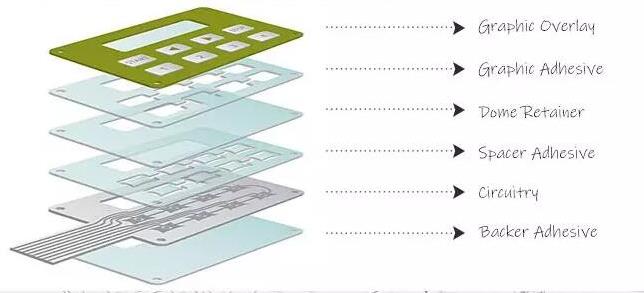
A membrane switch assembly differs from traditional mechanical switches. Membrane switches are essentially a sandwich of thin layers that are bonded together using pressure sensitive adhesives. The layers of a basic membrane switch construction include: a membrane overlay, spacer, printer circuit, rear adhesive, and tail filler. Other electronic components can be implemented, as well, such as discrete LEDs, backlighting sources, and connectors that make membrane switches easy to integrate into other systems or devices. Each layer in a membrane switch assembly serves a different purpose, and custom features require the addition of specialty layers. Depending on the environment and requirements of the application into which the membrane switch plugs into, the construction can vary.

Membrane Switch,Membrane Keypad Switch,Customized Membrane Switch,Custom Membrane Switch
CIXI MEMBRANE SWITCH FACTORY , https://www.cnjunma.com

