When it comes to power quality, you must know what is the reactive power compensation and voltage regulation of the power grid.
No matter how smart the smart grid is, first of all, as a power grid, it must ensure that the power it provides is of high quality and reliability. When it comes to power quality, it is inevitable to know what is the reactive power compensation and voltage regulation of the power grid.
This article refers to the address: http://
Reactive power is definitely very important for the design of the power grid system. This is actually a lot of content. It is a simple combing summary. There are some understandings in engineering practice, and I hope that they can confirm each other.
Reactive power corresponding voltage, active corresponding frequency, should be a relatively common understanding, of course, yes. Therefore, reactive power compensation and voltage regulation are inseparable, and they are also important indicators for dispatching assessment.
I. Overview and principles of reactive power compensationReactive power is relatively abstract, it is used to exchange electric and magnetic fields in the circuit, and is used to establish and maintain the electrical power of the magnetic field in electrical equipment. It does not work externally, but instead transforms it into other forms of energy. For electrical equipment with electromagnetic coils, reactive power must be consumed to establish a magnetic field. For example, a 40-watt fluorescent lamp requires more than 40 watts of active power (the ballast also consumes a part of the active power) to emit light. It also needs about 80 consuming reactive power for the ballast coil to establish an alternating magnetic field. Because it does not work externally, it is called "reactive."
The reactive power compensation and reactive power balance of the power system are the basic conditions for ensuring the voltage quality. First of all, some important principles are of course the principle of the State Grid. Although it is necessary to get rid of the shackles of the State Grid, some good things still need to be retained.
The principle of hierarchical partition compensation: In view of the large reactive power loss and the corresponding active power loss caused by the transmission of reactive power through a large impedance, the compensation arrangement of the reactive power of the power grid should adopt the principle of hierarchical partitioning and local balance. . The so-called tiered arrangement refers to the 220-500 kV power grid, which is the main active power and large capacity transmission. It is desirable to maintain the reactive power balance between the voltage layers, so as to minimize the reactive power between these layers. In order to reduce the large amount of consumption when transmitting reactive power through the grid transformer; the so-called partition arrangement refers to the power supply network of 110kV and below, which is suitable for realizing the division and local balance of reactive power.
Voltage qualification criteria:
500kV busbar: In normal operation mode, the maximum operating voltage shall not exceed +10% of the rated voltage of the system; the minimum operating voltage shall not affect the synchronous stability of the power system, voltage stability, normal use of the plant power and voltage regulation of the next stage.
220kV busbar of power plant and 500kV substation: In the normal operation mode, the voltage allowable deviation is 0~+10% of the rated voltage of the system; the accident operation mode is -5%~+10% of the rated voltage of the system.
110kV~35kV busbars of power plants and 220kV substations: In the normal operation mode, the voltage allowable deviation is -3% to +7% of the rated voltage of the corresponding system; after the accident, it is ±10% of the rated voltage of the system.
10 (6) kV busbars for substations and power plants (directly under) with regional power supply load: The allowable deviation of voltage in normal operation mode is 0 to +7% of the rated voltage of the system.
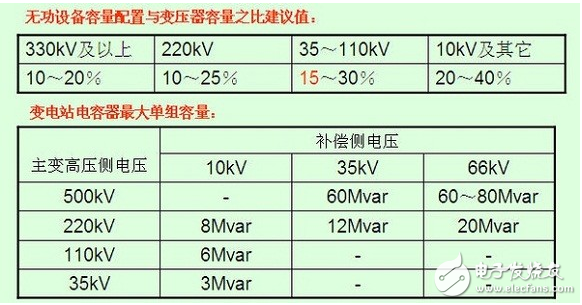
Reactive power compensation configuration principle: The grouping capacity selection of the reactive power compensation device of each voltage level substation should be determined according to the calculation. The maximum single-group reactive power compensation device should not change the voltage of the bus bar to exceed 2.5% of the voltage rating and meet the main When the maximum load is changed, the power factor is not less than 0.95.
The above is only a rough estimate. The reactive power configuration of the substation of a specific project needs to be calculated. The calculation is divided into different operation modes (for capacitive and inductive). The reactive power calculation is generally calculated together with the entire area of ​​reactive power exchange. It is related to regional load, power plant and external reactive input, and charging power of the substation in and out of the substation.
Measures to be taken for lack of reactive power:
All types of users are required to increase the power factor of the load to the value specified in the current regulations.
The reactive potential of the mining system. For example, the generator that is temporarily idle in the system is changed to the camera operation; the synchronous motor of the user is mobilized to perform the excitation operation.
According to the need of reactive power balance, the necessary reactive power compensation capacity is added, and the compensation capacity is allocated according to the principle of reactive power local balance. Small-capacity, decentralized reactive power compensation can be used for static capacitors; large-capacity reactive power compensation at the central point of the system should use synchronous camera or static compensator.
Voltage Hub Point: A node (busbar) that reflects and controls the voltage level of the entire system.
The reactive voltage control at the central point is very important. Generally, the following points are selected as the central point according to the actual situation: (1) the high voltage busbar of the large power plant; (2) the secondary busbar of the hub substation; (3) there is a large number of localities. Loaded power plant bus.
3) Transformer: A transformer is a device that consumes reactive power. In addition to the no-load reactive loss, when power is transmitted, reactive losses are generated by series impedance. For the reasons stated above, the transmission of a large amount of reactive power through the transformer should be avoided during operation, especially when the transformer short-circuit impedance is large. The voltage drop generated by the transformer transmitting power can be compensated by appropriately selecting the voltage tap of the transformer.
The voltage devices are mainly divided into three categories: power transformers, power plant boost converters, and grid connection transformers.
Power supply transformer: not only provides active power to the load, but also provides reactive power at the same time, and the short-circuit impedance is generally large. For transformers that directly supply power to the load center, it is better to configure a load-regulating tap. Under the premise of realizing the local balance of reactive power division, with the regional load increase and decrease, the regional reactive power compensation equipment parallel capacitor and The switching of the low-voltage reactor is to ensure the quality of the power supply voltage to the user at any time. This is stipulated in the guidelines of the State Grid Power System.
There is no uniform international practice for whether such transformers are to be automatically regulated with voltage. Because the effect of automatic voltage regulation of the transformer is not always positive, if the reactive power of the system is too large, it is necessary to maintain the voltage level of the load and adjust the voltage tap. It is bound to pass all the reactive power shortage to the main The power grid can cause major system accidents. For example, the power outage in France on December 19, 1978, the power outage in Sweden on December 27, 1983, and the cause of the Tokyo Power System blackout in Japan on July 23, 1987 were directly related to the automatic voltage regulation of the power transformer. . The essential reason is that this is only an indirect means, but it cannot change the equilibrium state of the system's reactive power demand.
Generator boosting: Whether this type of transformer is equipped with voltage tap and whether it has load regulating voltage tap, there is no conclusion, the generator itself is already a very convenient reactive power regulating device, and the voltage tap on the step-up transformer seems to be There is nothing special necessary. Of course, each system has its own traditional habits and practices.
Main network contact transformer: This type of transformer is characterized by large capacity, such as 500/220/35 main transformer. When studying whether this type of transformer should be equipped with a voltage tap with load regulation, there are two characteristics worth considering. First, the stratified balance of reactive power compensation and regulation capability determines the connection of the two main power grids. The contact transformer, in principle, should not undertake the task of exchanging a large amount of reactive power between layers, and the voltage change caused by the change of the active load alone is small. Secondly, because the connection is the main power grid, each The short-circuit current level of the side-to-transformer busbar is quite high, which will be much larger than the capacity of the transformer itself. The voltage tap of the regulating transformer has lost the effect of effectively adjusting the bus voltage. In 1982, the International Power Grid Conference Transformer Committee presented a report that specifically pointed out that with a load-regulated voltage tap, not only is it unreliable, but it also increases the complexity of the overall design of the transformer. Of course, this is not absolute and depends on the specific situation.
4) Shunt capacitors: Parallel capacitors have long been widely used in lower voltage supply networks and users, also known as low capacitance, to supplement reactive power. The biggest feature is that it is cheap and easy to install and maintain. Internationally, major power systems are constantly increasing and increasing the number of parallel capacitors, most of which are used to control the load power factor, and some are connected to the third side of the main transformer as a means of reactive compensation adjustment. A performance defect of a shunt capacitor is that its output power decreases squarely as the bus voltage drops, which can lead to a vicious cycle at low voltages.
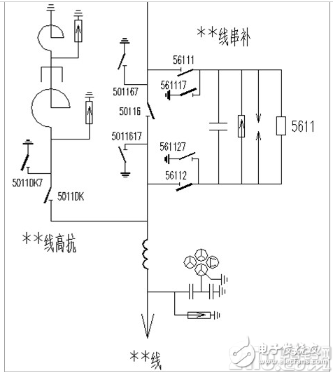
5) Parallel electric power: The shunt reactor is a device that absorbs reactive power. The 500kV line is directly connected to the line, which is called high impedance. The previous overvoltage part has already mentioned its function (restricting the power frequency and operating overvoltage, avoiding self-excitation, matching with the neutral point small reactance, can help the ultra-high voltage Long-distance lines are easy to eliminate arc during single-phase reclosing, thus ensuring single-phase reclosing success; 220kV lines are generally installed on the third side of the transformer windings, which is low impedance.
6) Series capacitor: Also known as series compensation, it is used to compensate part of the series impedance of the line, thereby reducing the reactive power loss when delivering power, and thus is also a reactive power compensation device. However, series capacitors are an important means to improve system stability and power transmission capability when power systems are transmitted over long distances. The South Network uses quite a lot.
The value of the terminal voltage boosted by the series capacitor QXC/V (that is, the voltage regulation effect) decreases as the reactive load increases and the reactive load decreases, which is exactly the same as the voltage regulation requirement. This is a significant advantage of series capacitor regulation. However, for a line with a high load power factor (cos φ > 0.95) or a small conductor cross section, the voltage regulation effect of the series compensation is small due to the large ratio of the PR/V component.
There are also some difficulties in using series compensation in high voltage systems. First, the complexity of the compensation station itself requires that the series capacitor and the protection of the series capacitor itself be reinstated immediately after the fault is removed. The zinc oxide varistor protection system developed in recent years has helped to solve this problem. Secondly, it has increased the difficulty of relay protection. Traditional distance protection has encountered some special problems in series compensation lines. It is necessary to solve the subsynchronous resonance problem that may occur in the series compensation circuit of the steam turbine generator set (this is an independent subject and there have been many accidents).
7) Synchronous camera: Synchronous camera is the first kind of reactive power compensation device, which is basically not used now. However, in order to adapt to the stability of the grid and the need for DC transmission, it still has its specific role in some cases.
8) Static compensator SVC: The static compensator consists of a power capacitor and a tunable reactance in parallel. The capacitor can emit reactive power, and the reactor can absorb the reactive power. According to the voltage regulation requirement, the reactive power of the capacitor group is absorbed by the adjustable reactor to adjust the magnitude and direction of the reactive power of the static compensation output. The static compensator can quickly and smoothly adjust the reactive power to meet the requirements of the reactive power compensation device. This overcomes the disadvantage that the capacitor as a reactive power compensation device can only be used as a power source and cannot be continuously adjusted. However, it does not apply to a power system where the receiving system is weak, because its capacity will decrease squarely as the bus voltage drops.
In essence, the static compensator is mainly a reactive power regulation method. Compared with the synchronous camera, although the cost is equivalent, the adjustment of the static compensator is far faster, 'this is a prominent advantage. In order to be able to exert its ability to quickly adjust the reactive power when needed, as for the voltage change caused by the normal load variation, the process is relatively slow, and it can meet the requirements by using a generally cheaper capacitor and a reactor. There is no need to choose this high performance device. Therefore, it is generally used for nodes with large load surges, voltage hub nodes, both sides of the tie line where power is easy to fluctuate, and accident emergency standby nodes.
As for the more advanced TCSC, STATCOM and other equipment mentioned in the future flexible power system.
Second, the system reactive power design1) The maximum long-term operating voltage allowed at each point of the system is limited by the insulation level of the connected power equipment and the saturation of the transformer. For example, in China, the maximum long-term operating voltage of a 500kV power grid is 550kV, and the maximum operating voltage of the transformer must not exceed 105% of the rated value of the corresponding voltage tap.
2) The minimum operating voltage at each point of the system is determined by the requirements for stable operation of the power system and the adjustment range of the transformer with load voltage tap. For power plants, it is also subject to the requirements of the plant.
3) For most foreign power systems, the allowable voltage fluctuation range is within ±5%-±10% of the rated value (normal and N-1 mode)
When designing the reactive power of a power system, there are some basic elements to consider:
Do not make the overload overvoltage of the UHV long-distance line exceed a certain allowable value (steady state power frequency overvoltage value)
Ensure the power transmission stability of the power grid. This is a limit on the minimum voltage level of the grid. In order to maintain a certain stability margin for all transmission lines in operation under various possible normal operation and grid operation modes after the specified event, it is required that the voltage of each hub substation can maintain a certain minimum level. Accidents generally consider N-1, and some consider serious N-2. There have been more than one major system accidents caused by voltage problems in the world. This will be mentioned in the future power grid blackouts, and the power system stability will also be involved.
The need for DC transmission. The commutation device of the direct current transmission will absorb the reactive power from the alternating current side when it is operated in the rectifier mode or the inverter mode. This part of the reactive power demand is quite large, and it is also a key consideration for the direct current transmission system.
The reactive power capability of the liberating generator and synchronous camera is reserved for emergency compensation after the event. If the parallel capacitor is used as the reactive power compensation at normal time, the task of correcting the voltage during normal operation is completed, and the rotating reactive capacity such as a generator is vacated as an accident standby. This is also a common practice in foreign systems.
For the emergency emergency problem of reactive power, it can be compared with the standby situation of the active power of the grid. In the arrangement of active power, sufficient peaking capacity, frequency modulation capacity, running reserve capacity, and automatic reduction of load by frequency reduction when a high power gap occurs must be left. The reactive power arrangement of the power grid has the same similar requirements in objective terms, but it has not been as clear as the active power. As far as the characteristics of the power grid are concerned, the biggest difference between the two is that for the frequency, the whole network is consistent, and the increase and decrease of the active power and the active load at any point in the power grid have basically the same effect on the frequency change of the power grid; It is regional or even point-by-point. The effects of reactive power and reactive load on voltage changes at various points are mainly local, so hierarchical partitioning and adjustment must be made to make reactive power and reactive load basic. Point by point. Therefore, when a large reactive power shortage occurs in the power grid, it is difficult to deal with it in the real life in accordance with the principle of dealing with the lack of active power. Therefore, this leads to the fact that in actual production, the reactive voltage regulation is quite difficult when a large accident occurs, resulting in serious consequences such as voltage collapse.
For high-voltage power grids, special reactive power planning needs to be formulated. In addition to small systems that are mainly supplied by regional power plants, it is generally necessary to coordinate the configuration of reactive power compensation equipment on a system-wide basis. In many systems, the first step is to determine the compensation capacity of reactive power according to the operating mode of the system peak load; then, according to the operation mode of the system low load, check the absorption capacity of the line charging power and its implementation means.
The design of reactive power compensation generally requires the study of three operating modes in the case of two major types of system structures. Two major types of system structure: normal and N-1; three modes of operation: large load, small load, and current flow reverse mode.
There are some details when the system is reactively designed:
The 500kV double-circuit line is suddenly disconnected during operation. The consequence is that the active power originally transmitted by the disconnected line will be immediately transferred to a line that remains in operation. Since the current remaining on the return line in operation suddenly increases, the reactive loss of the line will increase squarely. At the same time, it also lost the charging power of the original return line. This deficiency is not small and must be compensated immediately by the systems on both sides. The big power outage accident on December 17, 1983 in Sweden was caused by the failure of the main transmission line to trip and the lack of reactive power compensation.
In the operating grid, in order to solve such problems, it is possible to take a partial cut-off unit or, if the conditions are appropriate, to cut the part of the end load to reduce the transmission power in the reserved operating line to keep the event The system runs stably. However, such backup measures should be left to the production operations system to cope with events that may actually occur in more severe cases than when designing the system.
During the operation of the high and low voltage electromagnetic ring network, the high voltage line is suddenly disconnected for some reason. For example, 500kv and 220kV lines or 220kV and 110kV lines run in parallel. In China, this situation occurs in the early stage of the emergence of a new high-voltage grid. On such a parallel loop network, the active power is transmitted, and most of it will pass through the line on the side of the high-voltage network. If the active power of the transmission is large, when the high-voltage line in the ring network is disconnected due to the fault, the power transmitted through the parallel low-voltage line will immediately increase to much greater than its natural power, and the consequences may immediately cause stable operation. Sexual damage, or the terminal system voltage collapses, or the line is blown due to exceeding the thermal capacity power of the line. These accidents have occurred in more than one time in China's operating power grids, and they are serious post-accident operations. Therefore, this high and low voltage electromagnetic ring network must be avoided.
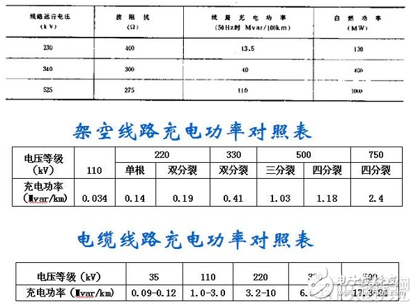
Whether to use the charging power of the 500kV line. Generally, it will not be used. Under light load conditions, whether using a high-voltage shunt reactor or a low-voltage shunt reactor, it is necessary to properly compensate. Compared with the situation of low voltage in the grid, for the production operation system, if there is no equipment condition, the high voltage of the grid will become an uncontrollable serious phenomenon. The long-term uncontrollable high voltage will bring great threat to the safe operation of power equipment.
The compensation capacity of the line high-voltage reactor can be considered to be about 70% of the line charging capacity. The long line can be set at each end of the line, and the short-term line can be installed only on the line side. Thus, when the line transmission power is about 55% of the natural power, the reactive power of the line itself is properly balanced, and when deviating from this value, the two sides of the system only need to provide a small reactive power compensation.
Third, the operating system voltage regulationThe control system's voltage control is to arrange and make full use of the reactive power compensation capacity in the power grid and adjust the capacity, keep the normal operation at any time, and the voltage value of each pivot point in the power grid does not exceed the specified limit cheek, and Ensure the safe and stable operation of the power system.
The main voltage regulator equipment : generators, transformers and other reactive power compensation equipment (such as shunt capacitors / reactors and SVC, etc.), DC transmission system.
The main means of voltage regulation : 1) adjust the terminal voltage of the generator, 2) adjust the tap of the transformer, 3) adjust the reactive switching capacity of the reactive power compensation device, 4) combine the generator, transformer and reactive power compensation equipment Pressure regulation.
The spatial range of voltage regulation : VQC control of a single power plant substation, AVC control of multiple plant stations, and global integrated reactive power coordination three-level control.
Time range of pressure regulation : static control of a single time period (single load level), multiple time periods (dynamic control of multiple load levels).
Among them, there are many researches on reactive power optimization, and there are many articles, but there are basically no applications in actual engineering. There are both operational problems and some adjustment principles that need to be clarified. For example, when the operating conditions change, to maintain the reactive power optimization of the system, according to the characteristics of the reactive power and voltage distribution of the power grid, it is necessary to require various reactive power regulating methods and voltage regulating means at various points of the whole system to frequently operate, and if not Highly developed power communication networks and automation conditions can't actually be done. For another example, unlike the frequency adjustment, the regulation and voltage regulation of the reactive power cannot be completely dependent on the synchronous machine and the static compensator, so that it is impossible to achieve uniform fine tuning; since it is impossible to establish a full-network voltage standard, it can only be in place. Based on the side voltage, these accumulated measurement errors are bound to affect the optimization, and so on.
A more realistic approach is to keep the voltages at various points in the system at an allowable high level under the premise of keeping an emergency emergency, so as not only beneficial to the operational stability of the system, but also to obtain economic benefits close to optimization.
A secondary voltage regulation system is also used to handle voltage problems in power systems in some countries. In the power grid, regional centralized control of reactive power and voltage, such as the French power grid, is very representative and useful. In the French system, there are three control layers (one time, two times and three times). In general, the rapid and irregular changes in voltage are compensated by the “one-time action†of the system power plant unit. This one-time effect requires fast (reaction time is a few seconds) and must be automatic. Mainly by the excitation adjustment of the unit, followed by the automatic voltage tap of the 400/225kV transformer. In order to deal with the slow change of voltage, the new state of the system is established by the "secondary" and "three times" control functions. The secondary control manages the dynamic reactive power that can be utilized in a region, and the reaction time is about 3 -5min, currently, the three controls are manual. Thereby achieving comprehensive coordination of voltages at various points throughout the system.
The operation practice confirms the advantage of the secondary control, that is, the voltage is well controlled under normal conditions. This actually leads to a research direction, that is, the control method of reactive voltage (distributed control, centralized control, coordinated control)
As for the important voltage stability problem, it will be summarized in the power system stability part and the large power outage part.
The reactive power and voltage parts are summed up so much. In fact, there are many aspects of reactive power involved in engineering practice. It is worthy of attention. I feel that I have not written everything I want to say. I think it will be added later. It is indeed the key content of system design.
Wireless Cpe,4G Cat6 Cpe,4G Mifi,4G Ufi
Shenzhen MovingComm Technology Co., Ltd. , https://www.movingcommiot.com