Design scheme of a remote intelligent medical monitoring system
0 Preface
With the continuous popularization of the Internet of Things and the widespread promotion of technology, the Internet of Things technology has had a profound impact on the medical and health industry. “Internet of Things Medicine†has become another focus of attention. “Internet of Things Medicine†was proposed by the Zhongshan Hospital affiliated to Fudan University to the domestic medical community at the 7th Shanghai International Respiratory Research Symposium.
The so-called IoT medicine refers to the use of sensing technology to fix the sensor on the human body. The terminal of the sensor is embedded and connected to the medical testing device. The doctor can connect to the terminal through a mobile phone or a computer, realizing the patient's all-weather, Remote detection and diagnosis.
1 remote intelligent medical monitoring system
In view of the all-round interconnection characteristics advocated by Internet of Things, this paper combines ZigBee and GPRS technology to make full use of network resources, and designs a gateway system for processing, transmitting and visualizing intelligent medical multi-monitoring parameters. The ZigBee wireless sensor network is formed by multiple blood pressure, body temperature, blood oxygen and pulse sensors. As a low-power, low-complexity, low-cost and auto-networking wireless network technology, ZigBee network supports sensor information collection, transmission and processing. It can communicate multiple sensor data at different points by using wireless network, and combine GPRS. The technology realizes remote monitoring, which changes the limitation of traditional wireless sensor network relying on wired public network for data transmission. It solves the problem of installing a large number of detection devices at the same time, large wiring volume, difficult line maintenance and modification, and makes the network show great advantages. .
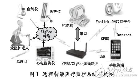
Figure 1 shows the architecture of the remote intelligent medical monitoring system. The system uploads information to the Internet cloud Yeelink platform through HTTP POST packets, enabling real-time collection, processing, visualization and remote monitoring of vital signs data.
The actual test results show that the system is stable and reliable, convenient for expansion and strong in real-time.
2 gateway node hardware design
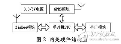
The intelligent gateway system based on STC12C5A60S2 is designed and implemented. The MCU is responsible for bidirectional data conversion between GPRS and ZigBee network. The gateway is actually a conversion gateway based on GPRS protocol and ZigBee protocol. In the ZigBee network, the gateway acts as a network coordinator. The main tasks include ZigBee networking, listening to the terminal, and two-way communication with the terminal. In addition, the gateway also bears the data between the GPRS protocol and the ZigBee protocol. Conversion, reception and transmission of GPRS network data, and processing of GSM short message queries.
The gateway hardware node circuit of the system is divided into a ZigBee communication module, a GPRS communication module and a power supply module. The hardware structure of the gateway is shown in Figure 2.
2.1 Power Supply Module
Since the required voltages for the ZigBee module and the GSM module are 3.3V and 5.5V, respectively, the system's power module converts the 9V voltage input to 3.3V and 5.5V for the processor and other modules. The characteristics of this mode: First, the system power module can leave enough margin, can provide up to 3 A current, thus preventing the power chip from heating up and burning due to excessive power output; the second is that the system passes the LDO chip LM2575- 5 and LM1117-3.3 two-stage step-down, designed power supply accuracy of 98%, ripple of 30 mV, to meet system requirements.
2.2 ZigBee Communication Module
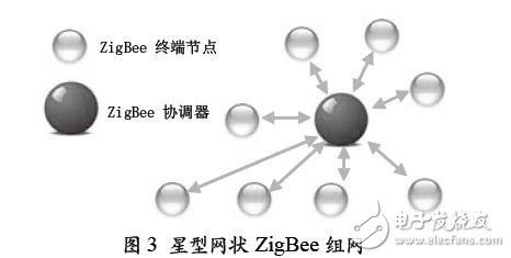
The ZigBee communication module is based on TI's CC2530F256 chip and runs the ZigBee2007/PRO protocol stack internally, with all the features of ZigBee. For the complex ZigBee protocol, this module embeds the protocol stack inside the module, leaving only the serial port. It does not need to consider the ZigBee internal protocol stack when communicating with the main control chip. It only needs to read and write the serial port to realize wireless transmission of data, which is easy to use. Can greatly reduce the development cycle. The ZigBee module can be connected to a PC via a serial port, with direct configuration parameters set to coordinator, router, and endpoint. The coordinator assigns a network address (16 bits) to the nodes that originally joined the network. Each ZigBee network requires a unique coordinator; the router can receive and forward data for routing and relaying; the terminal node is usually battery powered. Low-power device for collecting sensor data and sending data periodically. The ZigBee networking status is observed using the Sensor Monitor software. This gateway system uses a star network, so only the ZigBee coordinator and terminal nodes are used. Figure 3 shows a star-shaped mesh ZigBee network.
2.3 GPRS communication module
The GPRS module uses Longshang's A8000, which uses the baseband chip from Infineon, Germany, with super high receiving sensitivity. It is a dual-band 900/1800 MHz highly integrated GSM/GPRS module. The embedded TCP/IP protocol module is simple to use, supports GSM Rec.07.07/07.05 and its unique extended instruction set, and communicates directly with the MCU through the serial port through UART control.
3 gateway node software design
The software design consists of two parts: the gateway software and the monitoring center management software. The software development platform of the gateway is Keil C51, the ZigBee internally runs the ZigBee2007/PRO protocol stack, the ZigBee network monitoring software is SensorMonitor, and the monitoring center PC service management software development platform is the cloud Yeelink.
3.1 ZigBee/GPRS gateway programming
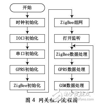
The program flow of the ZigBee/GPRS gateway is shown in Figure 4. After the system is powered on, the gateway node performs an initialization operation, then searches for an idle working channel, starts a ZigBee network, and waits for a connection request from the terminal node. After all the terminal nodes successfully join the ZigBee network, they enter the waiting state until the monitoring platform issues a data collection command, and the command is forwarded to all terminal nodes via the ZigBee network.
[Integrated Solar Street Lights"is a stand-alone solar lighting system conceived for outdoor residential and municipal lighting.Off- grid locations and ecologically sensitive areas.[Integrated Solar Street Lights"is designed for outdoor application in un-electrified remote rural areas. This system is an ideal application for campus and village street lighting, Farmhouses, Garden lighting etc.Housing Society, Institutional Parks, Pathway, Garden Lights etc.Highway Advertisement Signboards, Skywalks, Bus Stops, Railway Tracks.Chemical/Oil & Gas Ind. Power Plants, Marine areas, Coastal areas.
20W Integrated Solar Street Lights
20W Integrated Solar Street Lights,Integrated Solar Street Light 20W,Integrated 20W Solar Street Light,Integrated Solar 20W Led Street Light
Yangzhou Bright Solar Solutions Co., Ltd. , https://www.solarlights.pl