Design of hybrid emergency power supply system based on proton membrane fuel cell and lithium battery
China has a vast territory and frequent natural disasters. The emergency Power Supply equipment used in emergency rescue and emergency response is relatively cumbersome, noisy and emits harmful gases. Lithium batteries, nickel-metal hydride batteries, lead-acid batteries, etc. The power supply time is short and charging recovery is not available in emergency situations. This paper proposes an emergency power supply system using PEM fuel cell and lithium battery. When the hydrogen storage container is replaced, continuous power supply can be ensured. The control system adopts fuzzy algorithm, according to the SOC of the lithium battery, the optimal working state of the fuel cell and the load. , dynamic energy allocation and management. Developed a prototype used in emergency situations. The system has long continuous power supply (2 to 3 times of current equipment), no noise, zero emissions, and good results. It is an ideal emergency power supply for disaster relief and emergency response. equipment.
1 system composition
Fuel cell emergency power supply system.
The system consists of a 120W proton membrane fuel cell, a fuel cell controller, a lithium battery and a management system, and an energy tube unit. The lithium battery index is 13.2V/10Ah, to ensure the tactical requirements for emergency full power support 1h under fuel cell failure conditions or when fuel depletion is not possible. Fuel cell stack indicator: power is 120W, output voltage is 15V ~ 28V. The fuel cell controller mainly controls and monitors the stack temperature, input hydrogen and air pressure, flow rate, and stack abnormalities, and transmits information to the system controller through the CAN bus. The system controller mainly performs real-time detection on load size, lithium battery SOC and fuel cell stack conditions and dynamically performs energy management according to the fuzzy algorithm, so that the components of the emergency power supply system work in an optimal state to improve the efficiency and key components of the whole machine. Service life.
2 circuit design
2.1 charging and battery management circuit
The DC voltage is applied to pin 15 of the MAX1873 via isolation diode D5. Ql is a charging drive signal output switch. R4 is a charging current detecting resistor for detecting the magnitude of the output current. R2 is the detection resistance of the system current. R5 and R6 are output charging voltage adjustment resistors.
The 15V~28V voltage output from the fuel cell passes through the isolation diode D5 and the total current detection circuit, one through the R2, DC/DC circuit to the output, and the other through the Q1, inductors L1, D6 and R4 to charge the lithium battery. The voltage on R4 is proportional to the charging current. It is amplified by a voltage error amplifier and converted into a DC component. The microprocessor will output a reverse control voltage from pin 14 of the MAX1873 to reduce the on-current of Q1. If the current flowing through R4 is too small, the output voltage of pin 14 of MAX1873 will increase the current of Q1, which will make the battery pack have a constant current value. When the current is small and reaches the minimum charge current or 0, the MAX1873 outputs a low-level pulse control signal from pin 14, turns off BGl, and stops charging the battery. When the control input is low, BG2 is turned on, the charge control pin 6 pin (ICHG/EN) is low level, the 14 pin output is low level, BG1 is turned off, charging is stopped, and the charging current is only 1 μA. It is off (charging is disabled).
2.2 DC conversion and control circuit
The DC/DC converter circuit adopts XL4012 integrated converter, the input voltage is 3.6V~36V, the switching frequency of 2800kHz, the output voltage can be adjusted from 0.8V~28V, the conversion efficiency is up to 95%, the maximum output current is 12A, and the peripheral circuit is simple.
Emergency power supply system needs to detect more parameters: fuel cell output voltage, output current; charging and BMS charging current, battery voltage and battery SOC; output output current, output voltage. Therefore, it is necessary to expand the A/D interface, the system control adopts 89S51CPU, A/D adopts TLV2543 chip, the chip has 10 analog voltage inputs, and the serial interface with the single chip microcomputer occupies less port resources, the conversion speed is faster, the display adopts LCD1602 liquid crystal display, when the backlight is not used, the liquid crystal dynamic current is not more than 5mA, mainly showing the fuel cell working state, lithium battery SOC and charge and discharge, output voltage, output current information, machine efficiency and other power supply information.
3 fuzzy control algorithm
Let the fuel cell be at its best, while letting the lithium battery charge state above SOCmin. The output power of the lithium battery is adjusted based on the power share allocated to the fuel cell. For a lithium battery, when the minimum SOCmin limit (SOCmin) of the battery is less than or equal to 30%, the lithium battery must be charged; when the SOC is between 50% and 70%, depending on the power demand of the load, it can be charged or discharged; When the SOC is greater than 90%, it is not charged. The load power Pg and the lithium battery state of charge SOC are input variables of the fuzzy control, and the fuel cell distribution output power Pfc and the lithium battery output power Pb are output variables of the fuzzy controller. The fuzzy input variables Pg and SOC are based on [0,100]W and [30,90]%, and the input variables are blurred. The fuzzy subset is {ZO(zero), PS(positive small), PM (median) , PB (Positive)}; the fuzzy output variable Pb has a domain of [-100,110] kW, and the fuzzy subset is also {NB (negative large), NM (negative medium), NS (negative small), ZO (zero) ), PS (positive small), PM (median), PB (positive), the field of the fuzzy output variable Pfc is [0,110] kW, and the fuzzy subset is also {ZO(zero), PS (positive small) , PM (median), PB (Zhengda)}.
The fuzzy controller selects the membership function of the input and output fuzzy variables as the triangle with the load power Pg and the state of charge of the lithium battery. The fuzzy control rule is composed of a series of relational words. The most commonly used relational words are if-then, also, or and and determine the fuzzy control rules of each output and input quantity. The control quantity given by the fuzzy control algorithm needs to be carried out. Defuzzification is performed, and it is transformed into the basic domain that the control object can accept. The defuzzification algorithm uses the centroid method.
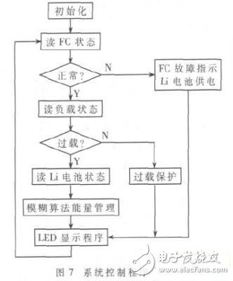
4 software design
The system control program flow chart is shown in the figure.
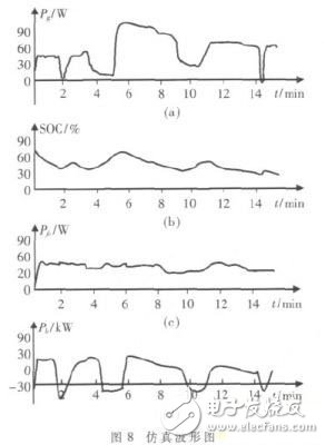
5 system simulation
The fuzzy controller is established in the Matlab simulation system. The target power Pg of the input variable of the fuzzy control and the state of charge SOC of the lithium battery are [-100,110]W and [30,90]%, and the fuzzy controller is taken. The output variables of the fuel cell distribution output power Pfc and the lithium battery distribution output power Pb are [0, 110] kW, [-100, 110] W, respectively. The lithium battery is 10 Ah/13.2 V, and the initial state of charge of the battery is SOC=60%. At the same time, the time taken in Matlab/Simulink is 0~15min, and the simulation waveform is shown in the figure.
6 prototype testing and evaluation
According to the SOC and load size of the battery, the fuzzy algorithm is used to dynamically allocate and manage the energy of PEM fuel cell and lithium battery. The prototype is developed. The actual test shows that the power supply efficiency of the whole machine is above 90%, and the specific power is 120W/500g. When the initial SOC of the lithium battery is 80%, the metal hydrogen storage tank with a capacity of 600 liters can be continuously supplied for about 16 hours. The continuous working hours and maintenance aspects have greatly improved the performance of the traditional emergency power supply equipment. At present, it has been industrialized and has great promotion value.
Equipped with A standard AC inlet IEC320-C8 (have no earth pin), the single phase ac to dc power adapters is developed the output power range to 12 wattage. Our green power range focusses on high active mode efficiency and low no load power consumption, complying with the latest global energy efficiency standards. 3 Years Warranty.
Wall plug Adapter,Cctv Adapter,Ac Adapter for POS,Ac Adapter,12V Adaptor,Dc Adapter
Shenzhenshi Zhenhuan Electronic Co Ltd , https://www.szzhpower.com