Texas Instruments experts share: medical ultrasound imaging power supply technology
Medical ultrasound imaging can be used to visualize viscera without penetrating the skin or radiating radiation to the body like some other imaging systems, such as endoscopy, X-ray computed tomography (CT) or X-ray imaging. In addition, ultrasound imaging is less expensive and easier to move than non-invasive magnetic resonance imaging (MRI). The growth in the use of ultrasound technology will be an important trend in the coming years.
Ultrasound systems (see figure) usually contain several key basic modules that increase the power requirements. Ultrasound probes contain up to hundreds of piezoelectric transducers. These piezoelectric transducers are capable of converting an output electrical signal into an acoustic wave or converting an input acoustic wave into an electrical signal.
In order to generate an electrical signal to be input to the transducer, a transmit beamforming device is required. The transmit beamformer is typically implemented by an FPGA or DSP. The transmit beamformer produces electrical pulses that are timed and adjusted to illuminate specific locations within the body.
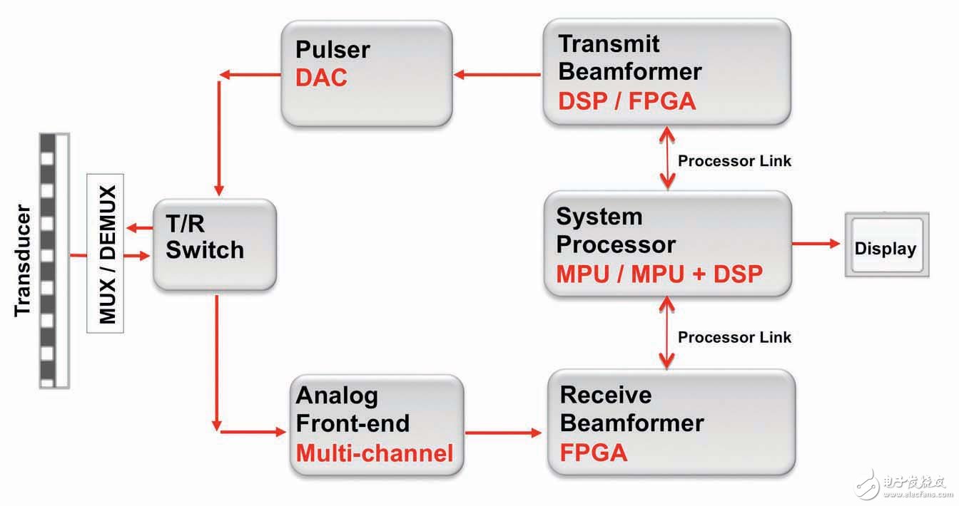
Figure important parts of the ultrasound system
These electrical signals from the transmit beamformer pass through a high voltage pulse generator or a high voltage D/A converter (DAC), and the energy generated is used to excite the transducer elements. There is a transmit/receive switch between the pulse generator or DAC. During transmission, it ensures that the low voltage receiving circuit is protected from high voltage damage because the receiving circuit also needs to be connected to the transducer.
Piezoelectric transducer elements convert these electrical signals into acoustic signals that can penetrate the human body. These sonic signals are reflected at various visceral edges and returned to the transducer.
These returned sound waves are converted into electrical signals as soon as they pass through the transducer. These lower voltage received signals need to be amplified, filtered and converted to a digital format to produce an image. Thanks to the development of the semiconductor industry, all of this can be done in one device: the analog front end (AFE).
The digital output will be loaded into the receive beamformer, which will reconstruct the data. After the image is rebuilt, it can be post-processed and form a format that can be output to the display for the technician to view the results.
Point of load power
Ultrasound imaging systems need to consider providing multiple supply voltages, and understanding the power requirements early in the design phase can save time building power architectures. When determining the system bus voltage, it is best to know the highest voltage required. An ultrasonic transmit pulse generator may require the highest voltage in the system, which requires several amps of current to drive the transducer.
12V is the most popular mid-range bus voltage option. It may be necessary to implement another set of power supplies to generate higher forward and negative voltages to power the pulse generator. If the ultrasound has a backup battery characteristic, it may require a higher voltage to charge the lead-acid or series/parallel lithium-ion (Li-ion) battery, then a mid-level bus voltage of 28 to 30V is a good choice.
There are many easy-to-use DC/DC switching regulators on the market that accept this voltage as an input and provide point-of-load (POL) power for displays, digital processors, and analog circuits. In addition, ultrasound imaging systems can be very susceptible to noise because they have sensitive high-precision analog circuitry and require clear display images. The Dc/dc switching regulator with frequency synchronization can be driven by the main clock frequency to eliminate beat frequencies that can interfere with analog and video signals.
Processor power
Ultrasound imaging systems use FPGAs, DSPs, and microcontrollers to implement beamforming transmit and receive functions, Doppler processing, and graphics processing. Powering the processor is simple.
However, the power supply of high-performance processors must consider some important factors. Processor manufacturers may specify minimum and maximum voltage ramp times, and many DC/DC regulators provide adjustable soft-start pins for programming ramp-up times. If no soft-start pin is available, select the DC/DC regulator with the appropriate preset soft-start time.
Recommended kernel, I/O, phase-locked loop (PLL), and time indicators for peripheral power-up timing are also provided in the processor data sheet. Although there are several different ways to power up and down the rail, sequential timing is the most common. This method is easy to implement, just connect the regulator's POWERGOOD pin to the enable pin of the next regulator.
Sequential timing also supports interleaving multiple voltage rails during power-up to minimize inrush current, rather than turning all voltage rails on simultaneously. Some low-dropout regulators (LDOs) and switching regulators offer a special timing or tracking pin that can accommodate almost any timing mode.
Lower processor core voltages drive the need for higher precision DC/DC converters. The new regulator claims to achieve a reference accuracy of ±1% or higher over the full temperature range. Low-cost regulators may specify a reference voltage accuracy of ±2% or ±3%. Please check the manufacturer's data sheet to ensure that the voltage regulation accuracy meets the processor's requirements. Early dc/dc converters that have been used for many years may not meet the voltage accuracy requirements of the latest processors.
Analog circuit power supply
The main analog components of the ultrasound system are the AFE, the ultrasonic transmit pulse generator, and the ultrasonic transmit/receive switch. These analog circuits, such as DACs, analog-to-digital converters (ADCs), and op amps (op amps) in high-precision instrumentation applications are very susceptible to noise and power supply ripple.
Noise is classified according to spectral noise density and output noise voltage (μVRMS). Power Supply Ripple Rejection (PSRR) refers to the amount of ripple at the output from the input ripple. Most designers choose linear regulators to provide clean voltage rails to maximize system performance. Linear regulators that advertise their PSRR and noise performance specifications on the data sheet home page are optimized for powering noise-sensitive analog integrated circuits.
AFEs, such as the AFE5808A, include an 8-channel voltage-controlled amplifier with a low-noise amplifier, gain-programmable amplifier, CW mixer, ADC, and other analog circuitry. The device requires several voltages to power various circuit blocks, such as 1.8, 3.3, and 5V.
The LDO regulator is suitable for powering these AFE voltage rails because the required current is small. To further improve efficiency and save board space, the switching regulators and LDOs packaged together can power high-sensitivity analog circuits. For example, the TPS54120 is a low-noise power supply that integrates a dc/dc converter and LDO. It supports up to 1A of current and provides an efficient switching regulator and a high PSRR LDO for a 5 or 12V bus with output noise as low as 17μVrms. .
Ultrasonic transmit pulse generators, such as the LM96550, contain eight high-voltage pulse generators with integrated diodes that generate bipolar pulses up to ±50V with peak currents up to 2A and pulse rates up to 15MHz. Because the transmit pulse generator also implements digital to analog conversion, another set of voltage rails is required to power the level shifter and low voltage logic.
A separate rail supply is required, and a buck converter (such as the TPS54060) in an inverter buck/boost configuration can easily derive positive and negative voltage rails from the mid-level bus voltage. Using a low current LDO on each voltage rail to help eliminate any switching noise from the inverter buck/boost converter is a good design.
The ultrasonic transmit/receive switch protects the AFE input of the low noise amplifier (LNA) from the high voltage pulses of the transmit channel. The input voltage is delivered by the output of the transmit pulse generator, while the LNA's output voltage is ±0.7V and the current is clamped at 1mA. Similar to a transmit pulse generator, this switch requires a separate rail supply for analog supply and negative high voltage bias supply. The bias supply must be the maximum negative supply voltage connected to the switch.
Ultrasound imaging systems include both analog and digital integrated circuits, both of which have different power considerations. Linear regulators provide low noise performance for analog circuits. Switching regulators offer higher efficiency and are generally better suited for powering high current, high performance DSPs.
Biomass Cook Stove,Wood Cook Stoves,Outside Camping Pellet Stove,Biomass Camping Stove
xunda science&technology group co.ltd , https://www.gasstove.be