Electric window anti-pinch design based on full bridge motor drive
In recent years, the growth of the automotive electronics market has been significant, mainly due to new applications such as enhanced vehicle performance, safety and comfort. To do this, it is necessary to install a large number of electronic modules and electronic harnesses at different locations in the car.
This article refers to the address: http://
Based on the principle of space saving and weight reduction, the automotive electrical system architecture is shifting from a single electronic control module and a centralized control system to a decentralized control technology. In addition, the reduction of assembly costs and the improvement of the reliability of the vehicle system require the transfer of previously used electromechanical operation functions into the electronic module. As a result, a series of standards for decentralized electronic modules have been produced, including more and more A wide range of standards-based automotive protocols (such as LIN and CAN) and their features (such as autonomous safe operation, diagnostics, protection and communication capabilities).
1, the window lifter principle
Currently, many automatic controls have the function of triggering a shutdown system, such as windows and doors. This also implies the danger of an accident, such as a part of the human body or animal being caught and pressed by these automatic devices. A specific example is the automatic window regulator of a car. Since the force exerted by the window glass on the obstacle is large enough, it is enough to crush a certain part of the body.
According to the recommendations of the relevant safety regulations, the automatic window lifting device must be equipped with the so-called "anti-pinch" function. The anti-pinch function means:
â– Detect the presence of obstacles when closing the window.
â– Limit the amount of force applied to the obstacle.
â– Move the window in the opposite direction to release the obstacle.
Existing solutions are not mechanical or mechatronic. In mechanical mechanisms, the anti-pinch detection is performed by a switch in an environmental sensor that is attached to the window post. The switch is normally turned off and turned on when pressure is applied to the environmental sensor. The solution is simple, but the sensor is expensive and potentially complicated to install and maintain. In some cases, this method cannot meet certain safety standards. For example, if the shape of the window is acute, the force is not applied to the surface of the sensor in a right angle (see Figure 1). Not touching the sensor, it is much more powerful than the standard requires.
There is an alternative to motor speed monitoring that performs functions through sensors (Hall effect sensors, encoders, etc.). Its anti-pinch environment detection is achieved by checking the change in motor speed. The motor is controlled by a relay that is powered by the entire battery. When the motor is started with maximum torque, the force applied to the obstacle can reach a maximum at startup. This article uses VNH2SP30 to monitor power variations due to motor load changes.
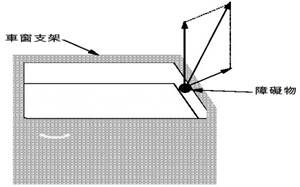
Figure 1. Car window schematic
The specific requirement for the window lift system is to detect the existing obstacle state during the start-up phase. The facts once again show that there are several situations in which a pinch accident can occur when the car window lifter is raised. The two most common possible scenarios are:
â– The window glass is located very close to the window pillars and the obstructing objects are located between the glass and the window pillars.
â– If the shape of the window mold is an acute angle, pinching is likely to occur in most cases (see Figure 1).
The power of the window lifter comes from a DC motor. It provides rotational motion directly and provides variable speed motion through coupling with the rotor and drum. The armature circuit and rotor shape are shown in Figure 2.
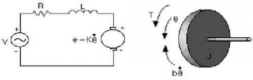
Figure 2. DC motor
Under normal conditions (soft start), during the start-up phase, the increase in motor power is proportional to its angular velocity and later increases with a constant. The possibility of pinching during the start of soft start is greater than the possibility of entering a steady state. Therefore, it is necessary to define two motor power thresholds that operate at different times during implementation. If the detected anti-pinch condition reaches the pinch threshold, the window glass stops during the descent to avoid an accident; if it is during the ascent, it will drop a fixed length.
2, hardware implementation
The design principle of the system is shown in Figure 3, and the specific embodiment is shown in Figure 8. The components used are as follows:
â– ST72F324 microcontroller: internal frequency is 8MHz, 32k bytes HDFlash, 1k byte RAM, 10bit ADC.
â– L4979 Regulator: For automatic recovery of data in the microcontroller when software fails, a programmable watchdog timer is also embedded in the device.
â– ST232 communication interface for PC serial port.
â– VNH2SP30 full-bridge motor driver for a variety of automotive electronics applications.
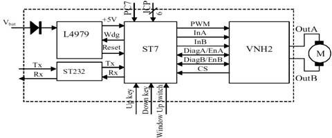
Figure 3 window lifter schematic
Among them, a voltage regulator is installed on the Voltage Regulator Enable connector (item 5 in Figure 4) to enable the regulator to provide the 5V required by the system.
The up button (Up key, item 8 in Figure 4) and the down button (Down key, item 7 in Figure 4) are configured to input pull-up mode so that they are normally at a high level (5V); Pressing the UP or DOWN button will display two different situations:
â– Short Touch: If the button is pressed for less than 100ms, the window glass will always rise or fall (depending on the button properties pressed) until the upper or lower edge of the window touches into place.
â– Long Touch: If the button is pressed for more than 100ms, the window will rise or fall according to the specific contact condition, depending on the properties of the button.
The Window Up switch pin (item 6 in Figure 4) is also configured for input pull-up mode and must be connected to a mechanical switch that indicates the end of window operation to see if it touches the upper limit of the door and window.
The microcontroller can be reprogrammed via the ICP connector (item 4 in Figure 4). The jumper on the PC7 connector (see item 9 in Figure 4) drives the VNH2SP30 through a PWM signal with a fixed duty cycle (50%) and frequency (20kHz). There is no anti-jamming function. When driving a window lifter with anti-pinch function, the PC7 jumper must be disconnected. The operation flow under the condition of anti-pinch function is shown in Fig. 5.
After powering up or restarting, the microcontroller initializes all used peripherals (input/output, timer, ADC, and SCI) and initiates an instruction that only stops resetting or turning off the line. Infinite loop.
Reset the anti-pinch identifier and the microcontroller will poll for each key pin. At this stage, the microprocessor operates in SLOWMODE mode to reduce power consumption.
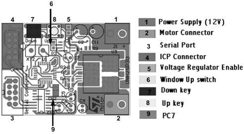
Figure 4. PCB layout
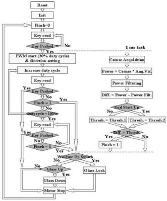
Figure 5. Anti-pinch function flow chart
Once the button is pressed, the selected mode will be the normal operation mode, and the INA and INB pins of the VNH2SP30 will be set or reset. The specific button is the up button or the down button. The Timer B Out Compare pin is used for the VNH2SP30. A PWM signal with a frequency of 20 kHz and a duty cycle of 30% is provided, and the Timer A Output Compare pin is used to perform tasks in a random manner with an execution time of 1 ms. During the 1ms mission execution, current sensing is acquired through the ST7 ADC with an average acquisition time of 10ms.
To know if a pinch will occur, the power and average power must be compared to the corresponding threshold. The size of the threshold considered depends on whether the rising start phase has been completed or that the soft start is still in progress. Unless a button is pressed or a pinch occurs, the duty cycle increases linearly to 100%, and the PWM becomes a constant (Figure 6).
At this point the system waits for the next event: a button press or a pinch occurs. If a button is pressed, the motor will stop running - reset the PWM pin of the VNH2SP30 and set the INA and INB to immediately stop the motor and stop the window glass. In the event of a pinch, the Window Up switch should be checked first.
If the glass reaches the upper limit of the window, the drive motor will run for 800ms to lock the window glass. Otherwise, if the glass is in the ascending process, the motor will go down for 800ms to release the clamped object; if the glass is in the down process, the motor will stop running.
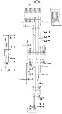
Figure 6. PWM signal of the VNH2SP30
3, PC interface
After the board is powered up, the VNH2SP30 is programmed according to the default values ​​of the relevant parameters (PWM, soft-start duration, two thresholds, or fixed PWM frequency and duty cycle). The above parameters can be modified or collected by using the serial port to exchange data between the PC interface and the VNH2SP30. When using the PC interface, it must be ensured that the motor has stopped.
The program mask can be seen from Figure 7, using the slider above the mask to make the following changes:
■PWM frequency: Possible values ​​are 5, 10, 15 or 20 kHz. The default value is 20 kHz. Some noise can be heard by lowering the frequency, depending on the motor used.
â– Soft start duration: The approximate range is between 800ms and 2.5s. The default value is 800ms.
â– Threshold 1: Used during soft start, specifically based on the window feature, the default value is 55. Increasing this threshold increases the amount of force applied to the obstacle before the anti-pinch action is initiated.
â– Threshold 2: Used after the start of soft start. The default is 20. As above, if this threshold is increased, the force applied to the obstacle before the anti-pinch measures are activated is increased.
If the PC7 jumper is installed, the microcontroller generates a PWM signal with a fixed frequency and a fixed duty cycle, where the frequency and duty cycle can be adjusted by adjusting the number in the data frame in the middle of the mask shown in Figure 7. achieve.
Press the “Send†button after setting all the values ​​so that you can use the new data the next time you drive the car window.
It is also possible to collect some signals every millisecond:
â– Instantaneous current: It is the current read from the CS pin of the VNH2SP30. The average duration is about 10ms, which is only used to ignore noise.
â– Complete current: It is also the current read from the CS pin of the VNH2SP30, but the average duration is about 100ms. It is similar to the instantaneous current waveform with just a delay.
â– Differential current: It is the difference between the above two currents and is the result of comparison based on the threshold.
After selecting any of the above options, press the "Send" button, which also changes the PWM frequency and soft start.
Signal acquisition can only be started by pressing the “UP†and “DOWN†keys on the board. It stops after pressing the “Acquis.Stop†button on the software. Once the signal acquisition is stopped, a ".csv" file will be generated in the directory where the software is installed. Each file generated consists of two columns: the first with time (ms) information and the second with the value of the signal.
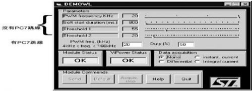
Figure 7. PC software

Figure 8 VNH2SP30 based window anti-pinch implementation plan
Dongyuan Syscooling Technology Co., Ltd. , https://www.syscooling.com