New concept of "start/stop" system helps save car fuel
Many car manufacturers have devised a clever way to save on car fuel by applying a new concept called the “start/stop†system. The system automatically shuts down the engine when the car is in a standstill or neutral position and restarts the engine as soon as the driver presses the clutch pedal again.
This article refers to the address: http://
The automatic start/stop function shuts down the engine every time the car is completely stopped and automatically re-starts the engine, thus helping to reduce fuel consumption and exhaust emissions. Compared to cars that are not equipped with such systems, fuel consumption can be as high as 8% in urban traffic environments. There is also an added benefit of being able to reduce its carbon dioxide emissions.
The principle is simple: if the engine is not running, it will not consume fuel. The auto start/stop system function will automatically shut down the engine when no engine work is required. In traffic jams or even stop-and-go traffic conditions, this function will be activated simply by placing the car in the neutral position and removing the foot from the clutch. A "start/stop" message on the information display will indicate "The engine has been shut down." If you want to restart the engine, press the clutch and gear, and the car will resume working quickly and you can continue driving immediately.
The automatic start/stop function does not affect the comfort and safety of driving. For example, the function will not be started until the engine reaches an ideal operating temperature. This principle also applies to situations where the air conditioner has not adjusted the car to the desired temperature, the battery is not fully charged, or the driver has turned the steering wheel.
The auto start/stop function is coordinated by a central control unit that monitors data from all relevant sensors, including the starter motor and alternator. The control unit also automatically restarts the engine for comfort or safety. For example, if the vehicle starts to travel, the amount of battery charge drops to a level that is too low, or condensation water forms on the windshield. In addition, most systems are able to distinguish between short pauses and the end of the journey. If the driver's seat belt is loose, or the door or trunk is open, the system will not restart the engine. If necessary, you can completely undo the auto start/stop function by pressing a button.
However, when the engine is restarted and an infotainment system is turned on or there are any other electronic devices that require a voltage greater than 5V, the 12V battery may be less than 5V, resulting in such a system reset. Some infotainment systems use a 5V and 8.5V operating input voltage that is fed by a buck converter that operates on a car battery. If the input voltage drops below 5V during engine restart, these systems will reset when the DC/DC converter can only step down the input voltage. Obviously, if the audio system is automatically reset each time the car is restarted during watching the video or listening to the CD, it will be unacceptable to the user.
A new solution
Fortunately, Linear Technology has introduced the LTC3859A, a three-output DC/DC controller that combines a synchronous boost controller and two synchronous buck controllers in a single package. The synchronous boost converter output feeds the buck converter to maintain a high enough voltage to prevent electronic systems that require operating voltages above 4V from resetting during engine restart. In addition, when the input voltage from the car battery to the boost converter is higher than its programmed output voltage, it will operate at 100% duty cycle and simply pass the input voltage directly to the buck converter. , thus minimizing power loss. Figure 1 shows the schematic of the LTC3859A, which provides a 10V supply from a synchronous boost converter to a synchronous buck converter when the battery voltage drops below 10V. In addition to powering the two buck converters (5V/5A and 8.5V/3A in this case), the boost converter can also be used as a “third output†to provide an additional 2A output.
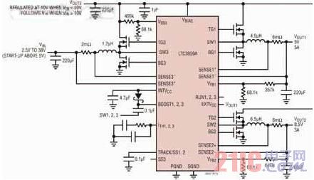
Figure 1: Schematic of a typical LTC3859A start/stop application circuit
The LTC3859A is a low quiescent current, current mode control, three output synchronous DC/DC controller with full N-channel MOSFET. At startup, the LTC3859A operates from an input voltage range of 4.5V to 38V and remains active after startup. As low as 2.5V. The two step-down controllers (Channels 1 and 2) operate 180° out of phase and produce an output voltage from 0.8V to 24V, making them ideal for powering navigation, infotainment systems, processors and memories. The step-up controller (channel 3) operates in phase with channel 1 and can generate an output voltage of up to 60V. A powerful 1.1Ω internal gate driver for each channel minimizes MOSFET switching losses. The operating frequency can be set from 50kHz to 900kHz or can be synchronized to an external clock with a frequency range of 75kHz to 850kHz using an internal phase-locked loop. The LTC3859A differs from the LTC3859 in that it has an internal clamp circuit on the INTVCC pin. This clamp circuit provides a fail-safe way to protect the INTVCC pin from excessive voltage when the user inadvertently uses a leaky Schottky limiting diode.
Other features of the device include built-in LDO for IC power and gate drive, programmable soft start, power good signal, and external VCC control. The VREF accuracy is ±1% over the -40°C to 85°C operating temperature range. The LTC3859A is available in a 38-pin SSOP package or a 38-lead 5mm x 7mm QFN package.
Extend battery life
Saving battery power is a must for any battery-powered system that requires a "always-on" power bus in the event that the rest of the system is turned off. This state is often referred to as the "sleep," "standby," or "idle" mode, requiring only a very low quiescent current. In automotive applications that may include many electrical circuits, it is particularly important to achieve low quiescent current in order to conserve battery power. In standby mode, the total current consumption of such systems must be as low as possible; and as automotive operations increasingly rely on electronic systems, the pressure on battery manufacturers to save battery power continues to increase.
In sleep mode (one of the boost converter and the two buck converters is on), the LTC3859A only sinks 75μA of current. When all three channels are on and in sleep mode, the LTC3859A draws only 100μA, which significantly extends battery run time in idle mode. This is accomplished by configuring the device to enter a high-efficiency Burst Mode operating state in which the LTC3859A delivers a short current pulse to the output capacitor, followed by a sleep cycle, which is only The output capacitor delivers output power to the load. Figure 2 shows a conceptual timing diagram illustrating how it works.
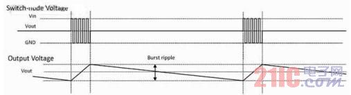
Figure 2: Burst Mode Operating Voltage Line Diagram for the LTC3859A
Burst mode output ripple is independent of load, the only thing that will change is the length of the sleep interval. In sleep mode, most of the internal circuitry is turned off, except for the critical circuitry used to achieve fast response, further reducing its quiescent current. When the output voltage drops sufficiently, the sleep signal level goes low and the controller resumes the standard burst mode operation by turning on the external MOSFET at the top. On the other hand, there are cases where the user wants the device to operate in a forced continuous mode or a constant frequency pulse skip mode under light load current conditions. Both modes are easy to configure, with higher quiescent current and lower peak-to-peak output ripple.
Load dump / efficiency / solution size
The term "load dump" refers to the inductive shock that occurs after the starter motor is turned off. For a 12V lead-acid battery system for automotive applications, this surge voltage is typically clamped at 36V (max). This surge requires the controller, MOSFET, and associated components to operate at the clamp voltage. These higher voltage devices (eg, 40V MOSFETs) can cause efficiency degradation and must be carefully minimized. When using the circuit in Figure 1, the efficiency of each voltage rail is higher than 92% (as shown in Figure 3). For the sake of clarity, the efficiency of each buck and boost section is shown separately. In addition, Figure 4 also shows the layout and dimensions of this circuit, with the highest component up to 4.8 mm.
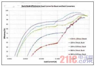
Figure 3: LTC3859A efficiency vs. load current (for different converter sections)
Start and shut down
The three channels of the LTC3859A can be individually turned off using the RUN1, RUN2, and RUN3 pins. Pulling any of these pins below 1.2V will turn off the main control loop for the corresponding channel. Pulling all three pins below 0.7V will disable all controllers and most of the internal circuitry, including the built-in LDO. In this state, the LTC3859A only absorbs 8μA of quiescent current.
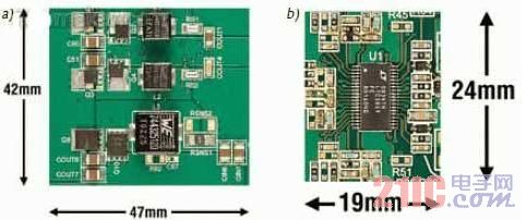
Figure 4: Dimensions and Layout of the LTC3859A Demo Board (a) Top (b) Bottom
Soft start or tracking
The TRACK/SS1 and TRACK/SS2 pins of the two step-down controllers can be used to adjust the soft-start on-time or “coincident†or “proportional†tracking of two or more sources during startup. These correlation curves are shown in Figure 5, and a resistor divider is placed between the main power supply and the TRACK/SS pin of the slave.
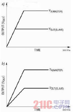
Figure 5: LTC3859A Output Voltage Tracking: (a) Coincidence Tracking (b) Proportional Tracking
Protective function
The LTC3859A can be configured to sense the output current using a DCR (inductor resistor) or a sense resistor. The choice of which of the two current sensing schemes depends to a large extent on the overall trade-offs of cost, power consumption and accuracy. DCR is gaining popularity because it eliminates expensive current sense resistors and is more efficient, especially in high current applications. The LTC3859A has a current foldback function for the buck channel to help limit the load current when the output is shorted to ground.
The built-in comparator monitors the buck output voltage and indicates an overvoltage condition when the output is greater than 10% of its nominal output voltage. When this condition is detected, the top MOSFET is turned off and the bottom MOSFET is turned on until the overvoltage condition is cleared. As long as the overvoltage condition persists, the bottom MOSFET will remain on continuously. If the output voltage returns to a safe level, normal operation resumes automatically.
The thermal shutdown circuit shuts down the LTC3859A at higher temperature conditions or when internal power dissipation causes excessive self-heating inside the chip. When the junction temperature exceeds approximately 170°C, the overtemperature protection circuit disables the built-in bias LDO, causing the bias supply to drop to 0V and effectively shut down the entire LTC3859A in an orderly manner. Once the junction temperature drops back to around 155 °C, the LDO will turn back on.
in conclusion
Fuel-saving car start/stop systems will continue to evolve over the next few years. Care must be taken in the power supply of in-vehicle infotainment and navigation systems, as well as the power supply of disk drives that require voltages of up to and even 5V for proper operation. Such systems reset when the input voltage drops out of regulation due to engine re-start. The LTC3859A provides a solution that boosts battery voltage to a safe operating level with its built-in synchronous boost controller. The LTC3859A combines a synchronous boost controller with two synchronous step-down controllers, making it ideal for powering a wide range of automotive electronics, maintaining regulation of all output voltages when the engine is restarted.
Grinder Machine,Surface Grinding Machine,Grinding Equipment,Tool Grinding Machine
Hunan Furui Mechanical and Electrical Equipment Manufacturing Co., Ltd. , https://www.thresher.nl