Common electronic component identification method inventory
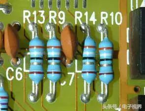
First, the resistor. In electronic circuits, resistors are denoted by the letter "R" followed by a number, such as R13 for a resistor numbered 13. The primary functions of a resistor include shunting, current limiting, voltage division, biasing, filtering (in combination with capacitors), and impedance matching.
Resistor symbol
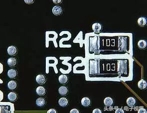
The unit of resistance is ohm (Ω), with larger units like kiloohm (kΩ) and megaohm (MΩ). The conversion is straightforward: 1 MΩ = 1000 kΩ = 1,000,000 Ω. Resistors can be labeled using three methods: direct marking, color coding, and numerical notation.
For example, in the digital standard method used for small surface-mount resistors, 103 represents 10,000 Ω (or 10 kΩ), where the first two digits are significant and the third digit indicates the number of zeros.
Chip resistor identification
Color coding is the most commonly used method for identifying resistors. A typical four-band resistor has the first band representing the first digit, the second band the second digit, the third band the multiplier, and the fourth band the tolerance. For example, a resistor with red, black, red, and gold bands has a value of 2000 Ω with a ±5% tolerance.
In cases where the color bands are unclear or misaligned, several techniques can help determine the correct order. One technique is to identify the tolerance band—usually gold or silver—which is typically at the end. Another is to check the spacing between bands, as the last band is often closer to the others. Additionally, the production series values can be used to verify the reading.
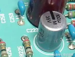
Second, the capacitor. Capacitors are usually marked with a "C" followed by a number, such as C223. They consist of two metal plates separated by an insulating material and are used to store electrical energy. Their main characteristic is blocking DC while allowing AC to pass through.
Capacitor on the board
The capacitance value determines how much energy it can store. The opposition to AC is called capacitive reactance, which depends on the frequency and capacitance. The formula is XC = 1/(2Ï€fC), where f is the frequency and C is the capacitance.
Common types include electrolytic, ceramic, chip, monolithic, tantalum, and polyester capacitors. Capacitance can be marked directly, via letters, or numerically. For example, 102 means 10×10² pF = 1000 pF, or 1 nF. Tolerance is also indicated, such as J for ±5%.
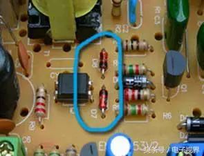
Third, the crystal diode. Diodes are represented by "D" followed by a number, such as D7. Their key feature is unidirectional conductivity, meaning they allow current to flow in one direction only. This makes them useful in rectification, isolation, voltage regulation, and protection circuits.
Diode representation in circuits
Diodes come in various types, including rectifier, switching, Zener, and Schottky. Identifying the polarity is simple—most small diodes have a colored band on the negative side. LEDs can be identified by the length of their leads, with the longer lead being positive.
Testing a diode with a multimeter involves checking its forward and reverse resistance. When the red probe is connected to the anode and the black to the cathode, a low resistance indicates a good diode. If the resistance is infinite, the diode may be open. Reverse testing should show high resistance.
Fourth, the inductor. Inductors are marked with "L" followed by a number, such as L3. They are made by winding insulated wire around a core and are used to store energy in a magnetic field. Inductors allow DC to pass but block AC, with higher frequencies encountering more resistance.
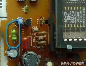
Inductor on the board
Inductors are measured in henrys (H), with common subunits like millihenrys (mH) and microhenrys (μH). They are often labeled using color codes similar to resistors, such as brown-black-gold-gold indicating 1 μH with 5% tolerance.
Fifth, the transistor. Transistors are denoted by "Q" followed by a number, such as Q1. They have two PN junctions and are used for amplification and switching. There are two main types: NPN and PNP, each with different characteristics.
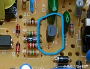
Transistor on the board
Transistors are used in amplifiers, switches, and signal processing circuits. Common models include 9012 and 9015 for PNP, and 9011, 9013, 9014, 9018 for NPN. Pin arrangements vary depending on the package type, with metal and plastic packages having different layouts.
phone Charging cable,Usb Phone Data Cable Android,iphone charge data cable,Phone data cable adapter
DongGuan BoFan Technology Co.,Ltd. , https://www.ufriendcc.com