Performance parameter analysis of DC power filter principle diagram
This article describes the schematic diagram of the DC power supply filter and its performance parameter analysis, and explains the structure of the DC power supply filter in detail.
DC power filterThe DC current filter is a filter suitable for the interference suppression of the input and output lines of the DC line. It adopts low line resistance, has the characteristics of low loss and high reliability, and conforms to the electromagnetic compatibility standard.
Design and Application of DC Power Filter1 Design principle-to meet the maximum impedance mismatch
The insertion loss should be increased as much as possible, that is, the signal reflection should be increased as much as possible. Suppose the output impedance of the power supply and the input impedance of the filter connected to it are respectively ZO and ZI. According to the signal transmission theory, when ZO≠ZI, reflection will occur at the input port of the filter, and the reflection coefficient
p=(ZO-ZI)/(ZO+ZI)
Obviously, the greater the difference between ZO and ZI, the greater p, and the greater the reflection generated by the port, the more difficult it is for EMI signals to pass. Therefore, the input port of the filter should be in a mismatched state with the output port of the power supply, so that the EMI signal is reflected. In the same way, the output port of the filter should be in a state of mismatch with the load, causing the EMI signal to reflect. That is, the design of the filter should follow the following principles:
If the internal resistance of the source is high impedance, the input impedance of the filter should be low impedance, and vice versa.
If the load is high impedance, the output impedance of the filter should be low impedance, and vice versa.
For EMI signals, the inductance is high resistance, and the capacitor is low resistance. Therefore, the termination of the power supply EMI filter and the source or load should follow the following principles:
If the internal resistance or load of the source is resistive or inductive, the filter interface terminated with it should be capacitive.
If the internal resistance or load of the source is capacitive, the filter interface terminated with it should be inductive.
2 Network structure of DC power filter
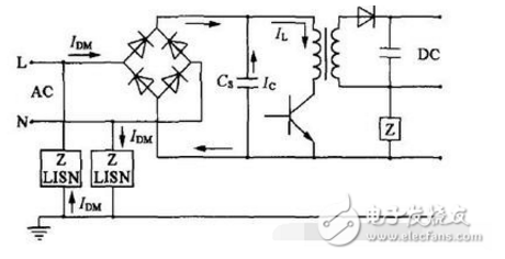
EMI signal includes common mode interference signal CM and differential mode interference signal DM. The distribution of CM and DM is shown in Figure 1. It can be used to guide how to determine the network structure and parameters of the EMI filter.
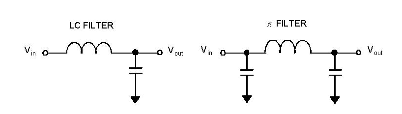
The basic network structure of the DC power filter is shown in the figure below.
The above four network structures are the basic structures of power supply EMI filters, but when selecting, pay attention to the following problems:
Two-way filtering function-the power grid should have a filtering function for the power supply and the power supply for the power grid.
It can effectively suppress differential mode interference and common mode interference-the main consideration is the suppression of common mode interference in engineering design.
Satisfy the impedance mismatch principle to the greatest extent.
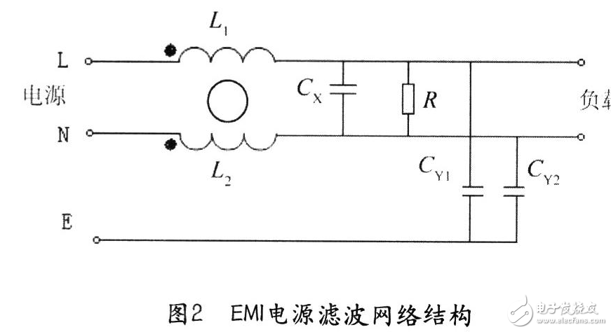
Schematic diagram of DC power filter
a) The value of the discharge resistance
When allowed, the smaller the resistance value is, the better, and the following situations need to be considered:
First, the resistance is required to be used with two-stage derating to ensure reliability. The derating factor is 0.75 V, 0.6 W. According to Ohm's law, n>(0.75Ve)2/(0.6 Pe) can be obtained.
Second, there is residual voltage after lightning surge, its instantaneous value is generally set at 1000 V; its instantaneous power value cannot exceed the rated value.
With 4 times the power value, R>(Vcy)2/(4Pe) can also be obtained.
The value of R is considered comprehensively. In general, the value of resistance R is between 75-200 K. The power is 2-3 W. Metal film resistors.
b) The value of Cx capacitor
If allowed, the larger the capacity requirement is, the better, and its value is difficult to accurately estimate. In general, the required value is between l-5uf (for each capacitor). The withstand voltage value of the capacitor must be taken after the lightning surge. There is residual voltage, and its instantaneous value is generally not damaged at 1000V/s. It is selected according to the principle of secondary derating, and the value is 275 V. The frequency characteristics and capacitance The value is related, the smaller the value, the better the frequency characteristic.
c) The value of Cy capacitor
If allowed, the larger the capacity requirement, the better, and its value is difficult to accurately estimate, but it can’t be too large. If it is too large, the leakage current will be larger. Under normal circumstances, the value is required to be between 2 200-4 700 pf (For each capacitor). The withstand voltage value of the capacitor must be taken after lightning surge. There is residual voltage, and its instantaneous value is generally not damaged at 1000V/S. It is selected according to the principle of secondary derating, and the value is 275 V. The frequency characteristics and capacitance are selected. The value is related, the smaller the value, the better the frequency characteristic. Cx capacitors and Cy capacitors generally meet the capacity requirements by connecting smaller capacitors in parallel, so that the high frequency characteristics of the filter are good.
d) The value of inductance
The selection principle of materials-consider from the following aspects:
First, the frequency range of the magnetic core material should be wide, and the highest frequency should be guaranteed at 1GHz, that is, there is a relatively stable magnetic permeability in a wide frequency range.
Second, the magnetic permeability is high, but it is difficult to meet this requirement in practice. Therefore, the magnetic permeability is often considered in sections. The core material is generally ferrite.
Estimation of inductance-considering impedance and frequency. The value of common mode choke is 1.5-5 mH, and the value of differential mode choke is 10-50uH;
DC power filter characteristics
1) Mainly used for electromagnetic interference of DC power lines;
2) It has excellent common mode and differential mode insertion loss in a wide frequency band (10KHZ-30MHZ);
3) High performance, low temperature rise, low price;
4) It can assist all kinds of electronic equipment using DC power to meet VDE and FCC standards.
summary
The metal shell of the filter must be in good contact with the chassis shell, and the grounding wire must be connected well.
There must be a certain distance between the input line and output line of the filter to avoid degradation of the filter performance.
It is better to use twisted-pair cable for the connection of the filter, which can eliminate some high-frequency interference.
The installation location of the filter should be the first choice at the entrance of the power supply to shorten the length of the input line in the chassis and reduce the radiation interference
The selection of the filter mainly considers its insertion loss. The curve given by the manufacturer is generally taken from the test result of a 50Ω system, but the actual application system is generally not 50Ω, and the insertion loss will have some deviations. In the actual application, the power filter It is a band pass filter, so pay attention to the influence of high frequency characteristics.
The second point of the filter selection is to pay attention to the working voltage, working current and leakage current, so as not to affect the use.
The low-frequency characteristic performance of the filter is related to the volume. If you want good low-frequency performance, you generally sacrifice the volume.
DC power filter technical parameters
Output impedance: 5(kΩ)
Input impedance: 10 (kΩ)
Stopband attenuation: 10 (dB)
Insertion loss: 30 (dB)
Reference temperature: 60(℃)
Excitation level: 50 (mW)
Load resonance resistance: 35 (Ω)
Load capacitance: 60 (pF)
Total frequency difference: 50 (MHz)
Temperature frequency difference: 10 (MHz)
Adjust the frequency difference: 55 (MHz)
Nominal frequency: 30 (MHz)
ConclusionThat's it for the introduction of DC power filters. I hope this article will give you a deeper understanding of DC power filters.
Sdec 21-75Kw Diesel Generator,Sdec Portable Power Generator,Sdec Open Type Power Generator,Sdec Container Power Generator
Shanghai Kosta Electric Co., Ltd. , https://www.ksdpower.com