Three examples show you how to compensate for diode drop variations
The diode forward voltage drop is as practical as diode rectification, which varies greatly with temperature, resulting in increased losses and tolerance errors in the power supply.
Although it is not possible to eliminate losses, diodes can be used to reduce tolerance errors in certain applications. This article will show how to achieve this goal through three examples.
You can build a simple low current regulator with a resistor and a Zener diode. This type of regulator is typically used for non-critical applications such as internal bias voltages. In general, the circuit will control the tolerance of the output voltage to within ±10%, but it is also possible to improve the regulation by connecting a diode in series.
Figure 1 shows a diode connected in series in a Zener diode circuit. The curve plots the temperature coefficients for the different voltages of the Zener diode. When the Zener diode voltage is greater than 4.7V, the temperature coefficient gradually becomes a positive number, so when the operating temperature rises, the Zener diode voltage increases. If paired with a diode with a negative temperature coefficient, by lowering the forward voltage of the diode, the increased voltage of the Zener diode is offset, eliminating temperature errors.
When the Zener diode voltage is less than 4.7V, the corresponding temperature coefficient is negative, and connecting a diode in series actually increases the adjustment error.
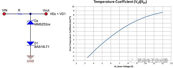
Figure 1: Connecting a positive temperature coefficient Zener diode in series with a negative temperature coefficient diode reduces the temperature error.
For example, a 7.5V Zener diode has a temperature coefficient of +5mV/°C, while a conventional diode (BAT16) has a temperature coefficient of about -1.6mV/°C at 10mA. When the diode current is very small, the temperature coefficient will gradually decrease (-3mV/°C), so be sure to check when the Zener diode has current. Ideally, the positive and negative temperature coefficients completely cancel each other out, but this is impractical and unnecessary, and simple improvements are sufficient. In the case where the diode has a high voltage and a positive temperature coefficient is higher, two (or more) diodes can be used to improve the cancellation effect.
Figure 2 shows the voltage regulation deviation and the different Zener diodes calculated in Figure 1 in the absence of a series diode, a diode in series, and two diodes in series for an operating temperature range of 25°C to 100°C. Comparison of output voltage. The vertical line in Figure 2 shows that the temperature-dependent error can be reduced by 3 to 5% at 7.5V output voltage after adding a series diode.
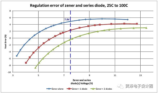
Figure 2: Connecting one or more diodes in series with a Zener diode with a voltage greater than 4.7V reduces the voltage regulation error.
In the second example, a converter is used which requires a level shifter to send output voltage information to the control circuit.
Figure 3 shows an inverting buck-boost circuit with a negative input to a positive output. The control circuit is based on the -Vin rail and the output voltage is referenced to ground. In order for the control circuit to precisely adjust the output voltage, the level shifter reconstructs the differential "Vout to GND" voltage between "FB and -Vin". In this implementation, a current source equal to (Vout - Vbe Q1) / R flows from Vout to Vin. The current flows in the lower resistance, reconstructing the output voltage based on -Vin. Adding Q2 and configuring it as a diode can restore the Vbe voltage drop loss generated by Q1. At this point, in addition to the small error associated with beta, the level shift voltage at the FB pin almost replicates the voltage between Vout and GND.
One benefit of adding a "diode" Q2 is that the forward voltage of Q2 can be very close to the voltage of Q1 because the current flowing through them is almost identical. To get the best voltage to match Q2, use the same resistor as Q1. Another benefit is that the two resistors have the same temperature coefficient, allowing the two to track each other's forward voltage more accurately. The temperature errors associated with Vbe changes are significantly reduced because they cancel each other out (VFB ~ Vout - Vbe Q1 + Vbe Q2). It is important to place Q1 and Q2 in adjacent locations because both are at the same temperature and, if possible, use a two-transistor package.

Figure 3: The level shifter uses Q2 to cancel the Q1 related changes.
The third example of Figure 4 shows a boost converter with a set of charge pump stages, with each stage "n" adding approximately "V1" to the total output, resulting in a result of "Vn + 1".
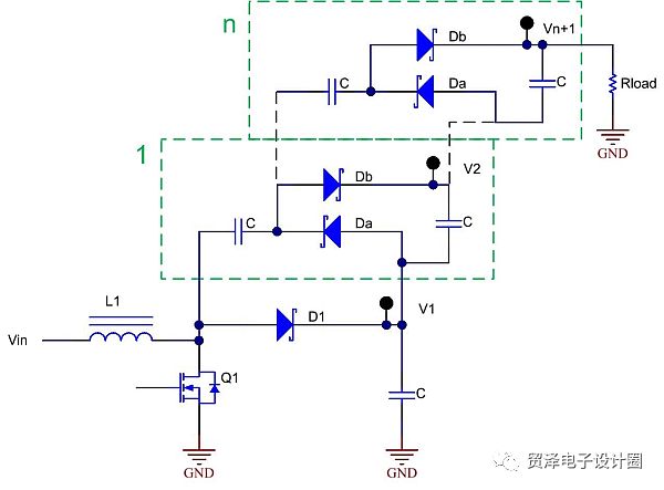
Figure 4: Charge pump diode drop can cancel each other out.
The approximate value of the total output voltage is:

In equation (1), it can be seen that Vn+1 is largely determined by a multiple of n, but is affected by the "error term" associated with the forward voltage drop of the diode and the ripple voltage of the charge pump switching capacitor. Reduced. Assuming all diodes are of the same type, their forward voltage is equal to:
VD1 = VDa = VDb, yielding equation (2):

In equation (2), the "error term" on the right makes the output voltage lower than the ideal n+1 times. To improve this, VDa and VDb use Schottky diodes, while VD1 uses a conventional diode with a forward voltage drop equal to:
VDa = VDb = VD1/2, yielding equation (3):

As can be seen from equation (3), it is possible to reduce the error term associated with the diode drop to further increase the output voltage. But equation (3) is still only an approximation, and the concept of output voltage increase is valid.
Diode forward voltage and temperature variations often degrade circuit performance, but not always. The methods shown in these design examples have the potential to offset or minimize diode temperature related errors.
Game machine harness advantages:
1).which is a full jamma harness with connectors for power supply, monitor, joysticks and buttons(microswitches).
2).It comes with edge connector, push button lugs, power lead, RGB monitor cable. Also includes extra button loom and connectors for all parts of your jamma.
3).We can make custom harnesses as customer request.
Game Harness,Blue Arcade Game Machine,Game Machine Wire Harness,Game Machine Harness
Dongguan YAC Electric Co,. LTD. , https://www.yacentercns.com