RF wireless module helps build a detailed tutorial on robot group control system
Science and technology always comes from human nature. It is said that science and technology are born of human desires. In the modernization of economic efficiency and efficiency, human beings further integrate computers and machines, create robots to increase work efficiency, or perform some dangerous work instead of humans. Therefore, the development of related technologies of robots will be more and more important.
The robot works developed in this paper are based on Holtek's eight-bit microcontroller (MCU), with functions such as metering, position estimation, infrared sensing obstacle avoidance, Chinese voice prompts, geomagnetic angle measurement, geomagnetic angle correction, etc. The computer (PC) or the notebook computer (Notebook) is used as the main control, and the human-machine interface main control program is written, and the radio frequency (RF) wireless module is used for communication, and the main control computer can issue instructions to the robot and receive the state return data of the robot. The theme of this paper is to apply this robot group control system to two robot formation transformations, which are horizontal and vertical formation transformation and four-corner formation transformation.
Master/controlled system architecture with RF transmissionAt present, the planned group robot group transformation is initially divided into two formations. The formation 1 is the exchange of multiple courses and the column formation. The formation 2 is the position transformation of the robots originally located in the four corners, although two There is no small difference in the schedule of the formation, but the system architecture is the same, which can be divided into the main control computer and the controlled group robot (Slave).
In this group robot action is completely issued by the main control terminal and then the action is executed, the action execution is completed, and then the action state is returned to the main control terminal; and the main control terminal decides the action of the group robot according to the return status of the robot, and the overall The architecture mode is shown in Figure 1. The communication between the computer-side monitoring interface and the controlled robot is based on the wireless RF communication platform, and uses the RS-232 communication protocol to wirelessly through the configured radio module nRF905. Radio frequency data transmission.
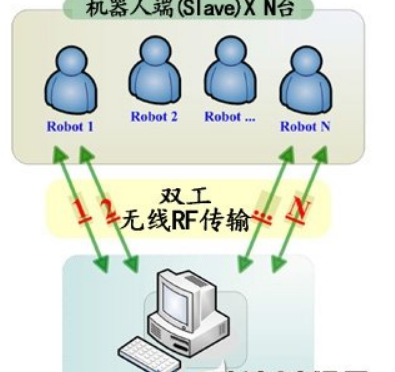
Figure 1 System Architecture
Wireless communication meets serial signal transmission requirementsThe wireless transmission part of the main control computer mainly uses RS-232 serial transmission and RxD pin, TxD pin and common pin of wireless RF module for data transmission. The main control computer has two ways and wireless RF module. Serial transmission, the first way (Figure 2), when the computer RS-232 transmission port is insufficient, we can use the computer's universal serial bus (USB) transmission port, USB to RS-232 designed by IC PL2303 The module converts the incoming data through the USB protocol into an RS-232 serial output signal, and then communicates with the RxD pin of the wireless RF module for communication data transmission and TxD pin for communication data reception, as long as attention is paid to each other's transmission waves. Whether the Baud Rate and the related communication protocol are the same, the command can be issued by the host computer to the wireless RF module or the signal sent back by the wireless RF module for wireless communication transmission; the second method (Fig. 3) When the computer RS-232 transmission port is sufficient, we use the RS-232 transmission port on the computer side, but the signal level based on the wireless RF module is 0 volts (V) or 5 volts. The voltage level of RS-232 on the terminal is +12 volts or -12 volts. The voltage levels at both ends are inconsistent. Therefore, IC HIN232 must be used for voltage level conversion. After conversion, you must pay attention to each other's Baud Rate and related communication protocols. Consistently, RS-232 serial communication transmission can be achieved.
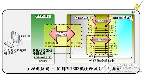
Figure 2 computer-side communication architecture-1
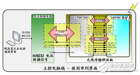
Figure 3 computer-side communication architecture-2
Direction Sensing Improves Robot Path Design AccuracyBefore designing the group-controlled robot path planning system (hereinafter referred to as the group-controlled robot system), the ability of the small robot will be improved first, including the direction sensing capability (adding the electronic compass sensing geomagnetic angle), the dodging obstacle capability, and the voice prompting capability. (Specific voice reporting function to inform the commander), robot walking path calculation ability (walking desired distance or calculating the distance of the traveled distance), and the ability to complete the data back-transfer capability (to facilitate the overall monitoring of the robot group by the computer) Etc., so that the basic functions of the robot itself are more in line with the functional requirements of the path planning.
The monitoring interface on the computer side is a wireless communication module that issues commands to multiple robots. Under this framework, how to make the monitoring interface more convenient and flexible for the master of the group control robot, so as to plan the path of the group control robot To help, the system will further plan the motion of the robot side as a single motion mode, multiple motion modes and synchronous motion modes by encoding the motion command data.
The action meaning of a single motion mode is to perform its own functions. If the robot receives the motion request, it immediately executes its motion command; the motion meaning of multiple motion modes is that the group robot starts at the same time and performs the same action; The action meaning of the mode is similar to the meaning of the single motion mode. When the robot receives the action command, the difference does not immediately execute the command request, and must wait for another synchronous start command, and then start and execute the command action that the robot has received at the same time.
Photosensitive module / electronic compass to help determine the direction of the lineAs shown in Figure 4, for the overall architecture of the robot, the environmental sensor has a photosensitive module and an electronic compass module, so that the robot has the ability of direction sensing, which will greatly help the robot in path planning; The accuracy of the Encoder pulse signal of the meter sensor reaches 0.185 cm, which improves the accuracy of the path planning. In addition, the infrared obstacle avoidance module can judge the obstacle and whether it reaches the intersection of the checkerboard experimental platform.
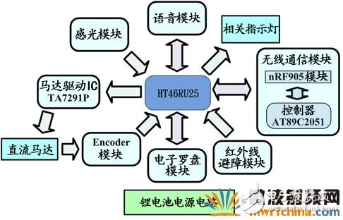
Figure 4 overall architecture of the robot
Figure 5 shows the human-machine interface of the group-controlled robot system. This monitoring interface is written by Borland C++ Builder. With this man-machine interface, commands can be given to the robots in the system, and when the robot executes the computer. After the command is issued, the execution result is transmitted back to the monitoring interface to achieve the purpose of monitoring the robot group.
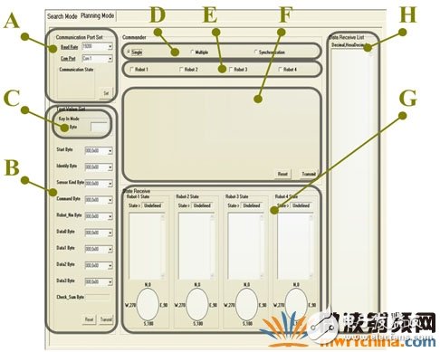
Figure 5 Group control robot system man-machine interface
Next, the numbers indicated in the figure are explained one by one. The number A is the corresponding setting of the communication port of the computer end and the wireless RF communication module. The setting content includes the RS-232 communication port selection and the Baud Rate selection, because the computer side person The machine interface is communicated externally by RS-232, so it is necessary to set this part first to activate the external data transmission action of the human machine interface; the number B provides the operator to select the data combination to be transmitted by the operator, and can also use the number. C keyboard input mode, after determining the data to be transmitted, press the transfer button to send the data.
The number D is the selection area of ​​the single, multiple, and synchronous action modes of the robot. When a single or synchronous motion mode is selected, the numbered E block will appear. The reason is that in multiple motion modes, it is not necessary to determine which robot is the robot. Receiving the action command data, so only one set of commands must be issued, so only a set of command selection windows will appear in the F part; the number F is the command selection field for each numbered robot; the number G block is the return data of each robot. The status display and statistical area, however, the group control robot system currently uses four robots. Therefore, four sets of individual display areas are planned, which are Robot-1 State to Robot-4 State; the number H block is displayed, and the computer receives Go to all the data from the robot back.
Path correction/avoidance detection/command receiving software is indispensableThe robot software design of the group-controlled robot system has functions such as single, multiple, and synchronous motion mode functions for path planning that enables the robot to facilitate the formation transformation application. According to the amount of exercise set by the computer-side monitoring interface, the forward, right-hand, back-reverse, and right-hand actions are performed, and the obstacle avoidance function is advanced. According to the amount of motion set by the computer monitoring interface, and according to the pulse width modulator (PWM) speed parameter, the forward, right-hand, backward, left-hand rotation and the like are performed, and when moving forward, the robot has a straight forward correction function.
The design can perform actions such as advancing, right-handed, rewinding, and left-handing according to the command of the computer-side monitoring interface, and calculating the total amount of motion. The robot faces the angle measurement (electronic compass sensing). The robot faces the angle correction function (according to the sensing value of the electronic compass). The voice prompt function, after performing the above actions, will promptly indicate the relevant status. After the status is returned, after executing the command, the relevant data will be transmitted to the computer monitoring interface.
Master the basic motion of group-controlled robots to effectively achieve path planning testThe purpose of this experiment is to test the monitoring interface of the group control robot path planning, whether it can smoothly issue work orders to four different numbered robots (including robot function tests in single, multiple, synchronous motion, etc.), and test whether the interface can be tested. Correctly display and count the information of each robot movement. These steps are necessary for the path planning of the group-controlled robot. It is possible to master the action state of the robot in order to effectively plan the path of the group-controlled robot.
As shown in Fig. 6, four robots are placed on the tabletop, from left to right, and the robots are numbered 1 to 4, and then the robots issue action commands one by one. Based on the single motion mode test described above, it is verified that the motion state of each robot can be monitored by the monitoring interface of the computer.
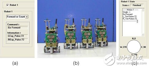
Figure 6 Single motion mode motion test. (a) The combination of the action commands transmitted by the monitoring interface, (b) the relative position after the robot performs the command action, and (c) the state return after the robot completes the action.
Cross-team change column/corner change is easyTo make the four robots change from the horizontal team formation shown in Figure 7(a) to the vertical queue formation of Figure 7(e), according to the synchronous command data of Table 1, one by one is issued by the monitoring interface, as shown in Figure 7(a). ~(e), the robot group will be gradually completed, and the path plan will be changed from the cross team to the column (each step is a synchronous action mode, so each step is executed simultaneously and executed), and the path planning is completed. The status of the return, as shown in Figure 8, contains the return mechanism that the robot receives the synchronization data. Therefore, it is verified that the synchronous command mode of the group-controlled robot path planning system is used to successively issue the action command, which can transform the robot group from the cross-team formation to the vertical team formation path planning. Here, the designer tries to complete the desired team with the shortest amount of movement. Shape transformation.
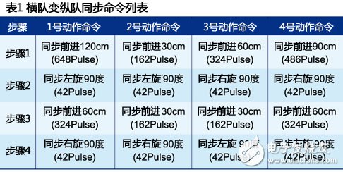
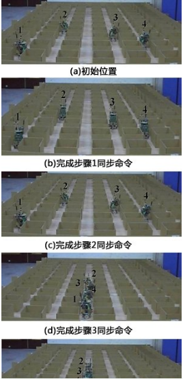
Figure 7 Cross-team change column path planning
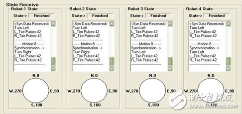
Figure 8 cross-border change column status return
In order to make the four robots change from the initial position shown in Fig. 9(a) to the final position of Fig. 9(h), the data can be integrated according to the multiple synchronization commands of Table 2, one by one by the monitoring interface. Released, as shown in Figures 9(a)-(h), the robot group will be completed step by step, and the diagonal cross-conversion formation (each step is multiple or synchronous action mode, therefore, each step is At the same time, it is started and executed, and the status of the path planning is completed, as shown in the column blocks of FIG.
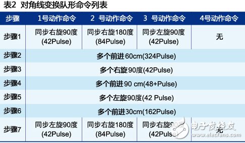
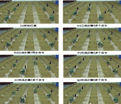
Figure 9 diagonal transformation formation

Figure 10 Diagonal transformation of the formation state back
It is verified that using the multi-synchronous command mode of the group-controlled robot path planning system, and sequentially issuing the action command, the robot group can make the path planning of the diagonal transformation position.
At present, the path planning of multiple robots can be classified into two major directions. One is the computer-side monitoring interface, which fully monitors the motion behavior of the robot, including the command from the computer to the robot, and the status of the robot to execute the command. Called the multi-robot path planning system.
in conclusion:After the actual test, and after determining that the function of the robot itself is normal, the monitoring interface is further integrated for testing, and it is found that the control of the single robot, the multiple, and the synchronous motion mode can be smoothly performed on the multi-robot end, and multiple and synchronized motion modes are proposed. The monitoring interface sends commands to the robot group, and performs the path planning method of the formation transformation, such as the cross-team change column, to verify the stability of the system, and can be used as the basic system for the subsequent multi-robot path planning extension experiment.
"Non-burning, nicotine for users, low tar content. As the heating temperature (below 500℃) is lower than the combustion temperature of traditional cigarettes (600-900℃), the harmful components produced by tobacco high-temperature combustion pyrolysis and thermal synthesis are reduced, and the release amount of side-flow smoke and environmental smoke (second-hand smoke) is also greatly reduced."
Heating non - combustion products are electronic devices containing tobacco. When you heat them, they produce a nicotine-containing vapor that you can inhale.
They are different from traditional cigarettes and work by heating tobacco to a very low temperature. Tobacco is heated to 350 ° C in a heat-incombustible device, while traditional cigarettes burn at up to 900 ° C.
Still, the temperature at which non-combustion products are heated is high enough to vaporize and inhale harmful chemicals.
Although both are electronic devices, heated non-combustible products are also different from e-cigarettes or steam devices. These usually use chemical liquids and do not necessarily contain nicotine. E-cigarettes tend to heat liquids to around 250 degrees Celsius to produce vapor.
Hnb Device Oem,Hnb Device Patent,Hnb Device,Hnb Device For Sale
Shenzhen MASON VAP Technology Co., Ltd. , https://www.masonvap.com