LPC2103 spi port drive 74595 8-bit digital display experiment
LPC2103 spi port drive 74595 8-bit digital display experiment
//
//System settings: Fosc, Fcclk, Fcco, Fpclk
//#define Fosc 12000000
//#define Fcclk (Fosc * 5)
//#define Fcco (Fcclk *4)
//#define Fpclk (Fcclk / 4) * 4
//Fpclk=60000000
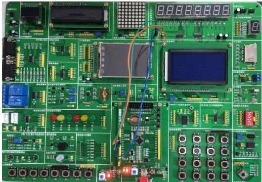
Wiring instructions: Use three 1P DuPont cables to connect the core board P04/P06/P07 to the backplane JP26
The specific wiring is: P04-SHCP, P06-DS, P07-STCP.
Jumper Description: Short J70
Experimental phenomenon: The digital tube sweeps first and then displays 0-9
************************************************** ***********
#define IN_MAIN
#include "config.h"
#include "LPC2103_lian.H"
#include "ADC.h"
#include "ExtInterrupt.h"
#include "I2C.h"
#include "IAP.h"
#include "Legacy_GPIO.h"
#include "RTC.h"
#include "SPI.h"
#include "SSP.h"
#include "Time.h"
#include "UART.h"
#include "WatchDog.h"
#include "ISR.h"
#pragma import(__use_no_semihosting_swi)
#define rclk_0() IO0CLR=IO0CLR|p07 //74959 latch clock
#define rclk_1() IO0SET=IO0SET|p07
Const uint8 tb[]={
0xfe, 0xfd, 0xfb, 0xf7, 0xef, 0xdf, 0xbf, 0x7f,
0xC0, 0xF9, 0xA4, 0xB0, 0x99, 0x92, 0x82, 0xF8, 0x80, 0x90,
0x88, 0x83, 0xc6, 0xa1, 0x86, 0x8e, 0x00,
};
Const uint8 smg_text[]={0xfe,0xfd,0xfb,0xf7,0xef,0xdf,0xbf,0x7f,};
Const uint8 smg[]={0xC0,0xF9,0xA4,0xB0,0x99,0x92,0x82,0xF8,0x80,0x90,0x00,};
// 0 1 2 3 4 5 6 7 8 9 all
Const uint8 smg_bit[]={0x01,0x02,0x04,0x08,0x10,0x20,0x40,0x80,0xff,};
Uint8 c;
Uint8 d;
Void IRQ_Exception(void)
{
}
//**********************Function Definition************************
Void delay(uint32 dly);
Void spiinit(void);
Uint8 senddata_mspi(uint8 uiData);
//**********************Main function************************ **
Void Main(void)
{
TargetInit(VPBDIV_DATA, PLLCFG_DATA, MAMTIM_DATA); // don't delete
While((PLLSTAT & (1 << 10)) == 0); // can delete
P04_sck0;
P06_mosi0;
P05_miso0;
P07_gpio; //Set the port to gpio port
Gpio_out(p07); // Set as output
Delay(1);
Spiinit();
For(d=0;d<8;d++)
{
For(c=0;c<8;c++)
{
Rclk_0();
Senddata_mspi(smg_bit[d]);
Senddata_mspi(smg_text[c]);
Rclk_1();
Delay(200);
}
}
While(1)
{
For(c=0;c<11;c++)
{
Rclk_0();
Senddata_mspi(smg_bit[8]);
Senddata_mspi(smg[c]);
Rclk_1();
Delay(200);
Delay(200);
Delay(200);
}
}
}
//********************* Initialize the SPI interface********************
Void spiinit(void)
{
SPI_SPCCR = 8; / / set the SPI clock divider, the value must be greater than or equal to 8 even (the greater the value, the lower the spi clock)
SPI_SPCR =0<<2 | // Transfer 8-bit data at a time
0<<3 | //CPHA=0, the first edge sampling. CPHA=1, the second edge sampling
0<<4 | // When the SPI bus is idle, CPOL = 1, the clock is high. CPOL = 0, the clock is low
1<<5 | //MSTR=1, set to master mode
0<<6 | //LSBF=0, SPI transmits MSB first
0<<7 ; //SPIE=0, SPI interrupt disabled
}
//******************spi send and receive data ******************
Uint8 senddata_mspi(uint8 uiData)
{
SPI_SPDR=uiData;
While((SPI_SPSR&0x80)==0); // Wait for the data to be sent
Return(SPI_SPDR);
}
//************************Delay********************** ****
Void delay(uint32 dly)
{
Uint32 i;
For(;dly>0;dly--)
{
For(i=0;i<5000;i++);
}
}
network cabinet is widely used for 19 inch network server enclosure perferated cabinet installing and placing of 19" international standard equipment and the system integration. Network Cabinets support large, modular network switches by providing additional space for cable management and side-to-side airflow solutions.
Network Cabinet,Electrical Cabinets,Wall Mount Server Cabinet,Wall Mount Server Cabinet,Wall Mount Cabinets,Electrical Distribution Cabinets
Sijee Optical Communication Technology Co.,Ltd , https://www.sijee-optical.com