How to work with stepper motor _ stepper motor selection method
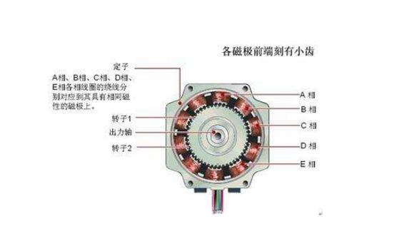
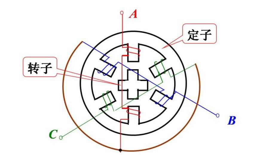
Usually the rotor of the motor is a permanent magnet, and when the current flows through the stator winding, the stator winding generates a vector magnetic field. The magnetic field causes the rotor to rotate an angle such that the pair of magnetic fields in the rotor coincide with the direction of the magnetic field of the stator. When the stator's vector magnetic field is rotated by an angle. The rotor also turns an angle with the magnetic field. Each time an electrical pulse is input, the motor rotates an angle further. The angular displacement of the output is proportional to the number of pulses input, and the rotational speed is proportional to the pulse frequency. Changing the order in which the windings are energized, the motor will reverse. Therefore, the number of control pulses, the frequency, and the energization sequence of the windings of each phase of the motor can be used to control the rotation of the stepping motor.
The principle of fever:The various types of motors commonly seen have iron cores and winding coils inside. The winding has resistance, and the power will generate loss. The loss is proportional to the square of the resistance and current. This is the copper loss we often say. If the current is not a standard DC or sine wave, harmonic loss will occur. The core has hysteresis. The eddy current effect also causes loss in the alternating magnetic field, and its magnitude is related to material, current, frequency, and voltage. This is called iron loss. Both copper loss and iron loss are manifested in the form of heat, which affects the efficiency of the motor. Stepper motors generally pursue positioning accuracy and torque output, the efficiency is relatively low, the current is generally large, and the harmonic components are high, and the frequency of the alternating current also varies with the rotational speed. Therefore, the stepping motor generally has a fever condition, and the situation is more general. The AC motor is serious.
Although stepper motors have been widely used, stepper motors are not as conventional DC motors, and AC motors are used under normal conditions. It must be composed of a dual ring pulse signal, a power drive circuit, etc. to form a control system. Therefore, the use of stepper motors is not an easy task. It involves many professional knowledge such as machinery, motors, electronics and computers.
How to maximize the efficiency of stepper motorsMany people use the two-phase stepping motor to find that the torque of the stepping motor is small, or the rated nominal torque value is not reached, and the size and nominal current of the stepping motor are increased to meet the power requirement. In fact, sometimes it is not a motor problem, but there is something wrong with the stepper motor selection or the setting of the operating current of the driver, and the maximum efficiency of the stepping motor is not exerted.
First of all, from the perspective of the driver, most of the current two-phase stepper motor drivers are four-wire connection using full-bridge output. If the two-phase stepper motor is also four-wire, the driver should be set according to the nominal current of the motor. It is correct, and the most efficient, the output torque can reach the maximum value, the new stepper motor is mostly in this form.
The early production of stepper motors is mostly two-phase six-wire (four sets of two pairs of series coils, each pair has a center tap), and a small number of eight-wire system (four sets of two pairs of independent coils).
There are two ways to connect the two-phase six-wire stepping motor. The first one is to abandon the center tap to connect the two ends. Actually, the two phase coils of each group are connected in series. The motor block torque is large and the efficiency is higher, but High speed performance is poor. The second type is connected to the center tap and one end. This type of connecting motor has better high speed performance, but each phase has a set of coils that are idle, with low blocking torque and low efficiency. Most of the current wiring methods are used. This raises a question as to how large the current of the two-phase driver should be set. Generally, it is set according to the nominal current value of the motor. This leads to the motor efficiency problem mentioned above.
Generally, the current marked by the stepping motor is the phase current (or resistance), which is the current value (or resistance) of each group of coils. If the two-phase six-wire stepping motor adopts the first connection method, it is equivalent to connecting the two sets of coils in series. As a result, the resistance of each phase is increased, and the rated operating current is reduced. Even if the driver is set to a nominal current, the rated output value of each phase cannot be achieved. Therefore, pay attention to the current matching problem when selecting the driver and stepper motor. The correct method is to set the output current of the driver to 0.7 times the rated phase current of the stepper motor (not the current that is normally considered to be halved in series). For example, for example, a two-phase stepper motor with a center tap, the nominal current is 3A, and the driver current should be set to 3 times 0.7=2.1A. Although a 3A stepper motor is selected, its power is equivalent. Two-phase four-wire 2.1A stepper motor.
Let's talk about the eight-wire stepping motor connection. There are two types. The first one is to use each two sets of coils in series, so that the current of the driver is also set to 0.7 times the motor phase current. The heat is small, but the high speed performance is poor. The second connection method is to use each two sets of coils in parallel, and the current of the driver is set to 1.4 times of the motor phase current. The advantage is that the high speed performance is better, but the motor generates a large amount of heat, but the stepping motor has a certain temperature is normal. As long as it is lower than the degaussing temperature of the motor, the degaussing temperature of the general stepping motor is about 105 degrees.
After using a stepper motor driver whose output current has been preset (refer to a two-phase full-bridge output driver such as TB6560, A3977, etc.), how to use a stepper motor is very important. If your drive is 2A, Try to use a two-phase four-wire 2A motor. If you choose a two-phase six-wire motor, you must select a motor with a nominal phase current of 2 / 0.7 = 2.9A (approx.). This will maximize the efficiency of the drive.
If the selected driver is a half-bridge output (such as SLA7062M, SLA7026 and other driver chips), it can only be connected to a two-phase six-wire motor, the current of the driver and the nominal motor current are the same. However, such drives are currently rarely used and are inefficient.
For the six-wire and eight-wire stepping motors, the phase coils are connected in parallel, which can exert the maximum output torque and exhibit good dynamic performance. The six-wire motor can not be connected in parallel, and the actual connection has been made internally. The common end of the series is the center tap. Only the phase coils of the eight-wire motor can be used in parallel.
If you can open the motor back cover, look at the wiring structure inside, you can make changes, make the six-wire motor into an eight-wire motor, so that it can be used in parallel, but not all six-wire motors can be modified, only It can be seen from the back of the motor that the form of the connection connector can be changed. Some motors are pad connectors. Restructuring requires a certain technology. The modified stepping motor can also be used in parallel in the original series. The phase current in parallel is 1.4 times, the high-speed running performance is greatly improved, and the torque is also improved. For the use of stepper motors and drives, you should pay attention to the best results, do not have to pursue high price and high current, and pursue high speed. You should carefully calculate the load of the machine to see how much torque and speed you need, otherwise Even if the drive and the motor are selected very large, the effect is not exerted, and the speed should not be too high. In the actual machining process, the machine feed amount is generally small (subject to mechanical structure, tool and material of processing materials). The speed is too high to be used.
Matching the motor and the driver can save money and effort, and achieve twice the result with half the effort.
In addition to quality in industrial production, production efficiency is the most important, because it directly affects the company's interests, so it is very necessary to improve equipment efficiency. The following is the method to improve the working efficiency of stepper motor reducer:
1. The machining accuracy of the stepper motor reducer is improved to ISO5-6;
2. Make the structure design of the stepper motor reducer more reasonable;
3. Improve the bearing quality and life of the stepper motor reducer;
4. The theoretical knowledge is becoming more and more perfect, and it is closer to reality (such as gear strength calculation method, shape modification technology, deformation calculation, optimization design method, root smooth transition, new structure, etc.).
1. Selection of stepper motor torque The holding torque of the stepper motor is similar to the "power" of the conventional motor. Of course, there are essential differences. The physical structure of the stepper motor is completely different from AC and DC motors, and the output power of the motor is variable. Which type of motor is usually selected based on the required torque level (ie the amount of torque required to carry the animal). Generally speaking, the torque is below 0.8Nm, and 20, 28, 35, 39, 42 (the diameter or square of the motor body, unit: mm) is selected; the torque is about 1N.m, and the 57 motor is more suitable. Torque force in several Nm or larger cases, it is necessary to select 86, 110, 130 and other specifications of the stepper motor.
2. The choice of stepping motor speed should also be specially considered for the motor speed. Because the output torque of the motor is inversely proportional to the speed. That is to say, the stepping motor has a low speed (a few hundred revolutions per minute or less, and its output torque is large), and the torque in the high-speed rotation state (1000 rpm - 9000 rpm) is small. Of course, in some working conditions, high-speed motors are required. It is necessary to measure the coil resistance and inductance of the stepping motor. A motor with a slightly smaller inductance can be selected as a high-speed motor to obtain a larger output torque. On the contrary, in the case of low speed and large torque, it is necessary to select the inductance at ten or tens of mH, and the resistance should be larger.
3. Selection of no-load starting frequency of stepping motor The no-load starting frequency of stepping motor is usually called “empty frequencyâ€. This is an important indicator for purchasing a motor. If it is required to start and stop frequently in an instant, and the rotation speed is around 1000 rpm (or higher), "accelerated start" is usually required. If you need to start directly to achieve high speed operation, it is best to choose a reactive or permanent magnet motor. The "empty frequency" of these motors is relatively high.
4, the number of phase of the stepper motor selects the number of phases of the stepper motor, this content, many customers have little attention, most of them are purchased casually. In fact, different phases of the motor, the work effect is different. The more the number of phases, the smaller the step angle can be, and the vibration at work is relatively small. In most cases, there are more two-phase motors. In the high-speed and high-torque working environment, it is more practical to select a three-phase stepping motor.
5, for the stepper motor use environment to choose a special stepper motor can be waterproof, oil-proof, for some special occasions. For example, underwater robots require a water discharge motor. For special-purpose motors, it is necessary to select them.
6. According to your actual situation, you can need stepping motor with special specifications and special specifications. Please communicate with us and process the order within the scope permitted by the technology. For example, the diameter, length, and extension direction of the shaft.
7. If necessary, it is best to communicate and confirm the model with the technical engineer of the manufacturer.
Resistive Touch Screen
The outermost layer of resistance screens is usually a soft screen that connects the internal contacts up and down by pressing. The inner layer contains the oxidized metal of the physical material, namely N-type oxide semiconductor (indium oxide), also known as indium oxide, with an optical transmittance of 80% and the upper and lower layers separated by the middle. ITO is the main material used in both resistive and capacitive touch screens. Their working surface is the ITO coating. The outer layer is pressed by fingertips or any object to make the surface film concave and deformed. According to the leading line number of screen, divide again have 4 line, 5 line and much line, threshold is low, cost is opposite cheap, advantage is not affected by dust, temperature, humidity. Disadvantages are also obvious, the outer screen film is easy to scratch, can not use sharp objects to touch the surface. In general, multi-touch control is not allowed, that is, it can only support a single point. If two or more contacts are pressed at the same time, they cannot be recognized and accurate coordinates can be found. To enlarge a picture on the resistance screen, you can only click "+" several times to make the picture be enlarged step by step. This is the basic technical principle of the resistance screen.
Control by pressure induction. When a finger touches the screen, the two conductive layers are in contact at the touch point and the resistance changes. A signal is generated in both X and Y directions and transmitted to the touch screen controller. The controller detects the contact and calculates the position of (X, Y), then works according to the simulated mouse mode. Resistive touch screen is not afraid of dust, water and dirt, and can work in harsh environments. But because the outer layer of the composite film is made of plastic material, its anti-explosion property is poor, and its service life is affected to some extent.
The resistive touch screen is controlled by pressure induction. The surface layer is a layer of plastic and the bottom layer is a layer of glass, which can withstand the interference of harsh environmental factors. However, it has poor hand feel and light transmittance, so it is suitable for wearing gloves and occasions that cannot be touched directly by hand.
Resistive Touchscreen,Resistive Screen,Resistive Touch,Resistive Touch Panel
TONYA DISPLAY LIMITED , https://www.tydisplay.com