TI TIDA-01179 30W Automotive Front End Power Reference Design
TI's TIDA-01179 is a 30W automotive front-end power supply reference design that includes two DC/DC converters: the first is a buck-boost DC/DC converter that meets ISO 7637-2 and ISO16750-2 standards; The second is a low-cost, compact buck converter with up to 20W output. The system also includes reverse battery protection, electrical transient protection and EMI filters. The reference design handles all battery conditions, input voltage 3-36V DC Mainly used in HEV/EV traction inverter, electronic control unit, battery front end power supply and dry double clutch transmission. This paper introduces the main characteristics of the reference design TIDA-01179, block diagram, HEV/EV traction inverter system block diagram and reference Design TIDA-01179 circuit diagram, bill of materials and PCB design.
This reference design is an automotive front-end power supply that can supply a 30-W maximum output for the 12-V car battery. The first stage is abuck-boost DC/DC converter, which maintains a stable output voltage over the full DC range of The 12-Vbattery conditions specified in ISO 7637-2 and ISO16750-2 standards. Then a low-cost, compact buckconverter is connected to the buck-boost converter and enables up to a 20-W output. The system consists of reverse battery protection, electrical Transientprotections, and EMI filters. The EMI filter consists ofDM and CM respectively and is designed forcomplying conducted EMI standards per CISPR25.
This reference design is a wide input 30-W front-end power supply for a 12-V car battery in the HEV/EVtraction inverter system. It consists of two DC/DC converters. The first converter is a buckboostconverter, which handles a wide The input range from the car battery and provides 15 V of constant output voltage at a 2-A output current. This 15-V rail can be used to power the system basis chip (SBC), the resolver, and the primary of the IGBT bias supply Then a buck converter connected to the output of buck-boost converts the 15 V down to 5 V at 4.5 A. This 5 V can power the microcontrollers, ADconverters, safety diagnostic circuits, the primary sides of the current sensing, voltage sensing, and So on.
The TIDA-01179 is able to handle all battery conditions, which includes:
• The system maintains a constant output voltage over the full DC range of battery conditions specified in ISO 16750-2:
– Input VIN(min) down to 3.0 V simulating a severe cold cranking condition
– Input VIN(max) up to 28 V simulating the upper range of normal battery operation
• The system must clamp and filter high-voltage electrical fast transients and maintain operation throughthem:
– These pulses include clamped load dump (up to 38 V) and other transients outlined in ISO 7637-2:2004.
• The system must properly respond to a reverse battery polarity event and shut down.
• Filter design targets at the CISPR 25 automotive EMI standard for conducted emission suppression.
• The layout of the board must be done in such a way to minimize the footprint of the solution whilemaintaining high performance.
Reference design TIDA-01179 main features:
• Wide-VIN Buck-Boost Converter During Very LowDips in Input Voltage of 3- to 36-V DC, 42-VTransient
• Low-Cost Buck Operates After the Buck-Boost With5-V and 4.5-A maximum output
• Reverse Battery Protection With Fast Shutdown
• Designed and Tested for Severe Battery ColdCrank Operations (ISO 16750-2 Level III)
• Designed and Tested for ISO 7637-2:2004 Pulse 1,2a, and 3a/b Severe Conditions (Level IV)
• Tested for CISPR25 Conducted EMI (Class 5)
Reference Design TIDA-01179 Application:
• HEV/EV Traction Inverter
• Dry Double Clutch Transmission
• Electronic Control Units
• Battery Front-End Power
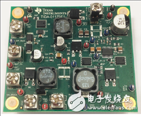
Figure 1. Reference design TIDA-01179 outline drawing
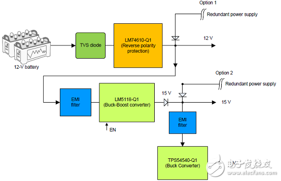
Figure 2. Block diagram of the reference design TIDA-01179
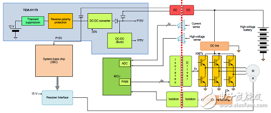
Figure 3. Block diagram of the HEV/EV traction inverter system and the location of the TIDA-01179
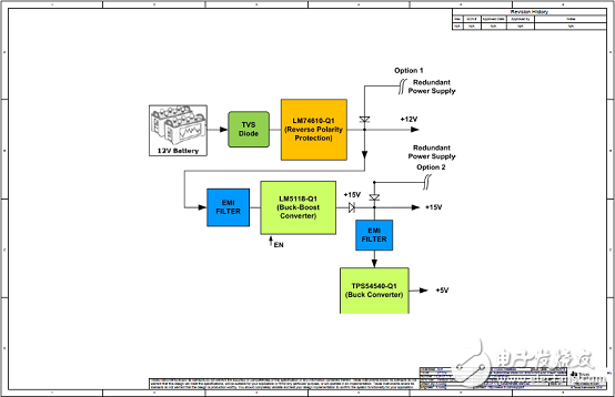
Figure 4. Reference Design TIDA-01179 Circuit Diagram (1)
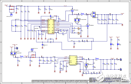
Figure 5. Reference Design TIDA-01179 Circuit Diagram (2)
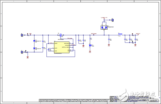
Figure 6. Reference Design TIDA-01179 Circuit Diagram (3)
Reference design TIDA-01179 material list:
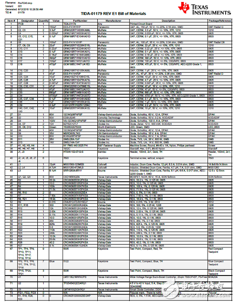
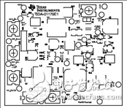
Figure 7. Reference Design TIDA-01179 PCB Design Drawing (1)

Figure 8. Reference Design TIDA-01179 PCB Design Drawing (2)
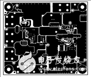
Figure 9. Reference Design TIDA-01179 PCB Design Drawing (3)
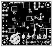
Figure 10. Reference Design TIDA-01179 PCB Design Drawing (4)
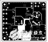
Figure 11. Reference Design TIDA-01179 PCB Design Drawing (5)
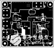
Figure 12. Reference Design TIDA-01179 PCB Design Drawing (6)
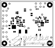
Figure 13. Reference Design TIDA-01179 PCB Design Drawing (7)
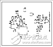
Figure 14. Reference Design TIDA-01179 PCB Design Drawing (8)
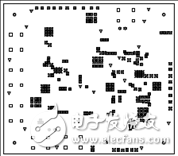
Figure 15. Reference Design TIDA-01179 PCB Design Drawing (9)

Figure 16. Reference Design TIDA-01179 PCB Design Drawing (10)
Stainless Steel Non-Magnetic Wire
Stainless Steel Non-Magnetic Wire,Cable Wire Railing Stainless Steel,309L Flux Core Wire,Marine Grade Non-Magnetic Stainless Steel Wire
ShenZhen Haofa Metal Precision Parts Technology Co., Ltd. , https://www.haofametal.com