Vehicle radar transceiver frequency modulation system and chip solution
As the basis of radar hardware and software design, the choice of transceiver frequency modulation system plays a key role in the core indicators such as ranging, speed measurement, range finding, resolution, accuracy and ambiguity. There are currently few systematic introductions to automotive radars. This article will introduce the most commonly used methods of transmitting and receiving FM systems in mass-produced vehicle-mounted radars.
In recent years, the loading rate of advanced driver assistance systems based on microwave radar has risen rapidly. Common applications include forward collision warning FCW, adaptive cruise ACC, automatic follow-up S&G, and backward blind zone detection BSD, lane change assistance. LCA, lateral detection of CTA, and the like.
Although the focus of each application is different, in general, the on-board radar provides drivers with timely and reliable warning information by measuring the distance, relative speed, angle, size, and number of targets. The rapidly evolving market requires automotive radars to have farther measurement distances, wider detection angles, higher ranging speed direction finding accuracy, shorter detection times, more detection targets, and more reliable detection rates.
The above requirements need to be uniformly upgraded at the system level, including antenna, RF, baseband hardware design, transmit frequency, sweep bandwidth, waveform modulation, baseband algorithm, and so on. As the basis of radar hardware and software design, the choice of transceiver frequency modulation system plays a key role in the core indicators such as ranging, speed measurement, range finding, resolution, accuracy and ambiguity. There are many articles on the market that introduce radar-like FM systems, but there are few systematic introductions to automotive radars. This paper gives a brief introduction to the most commonly used methods of transmitting and receiving FM in mass-produced on-board radar:
Variable slope continuous wave radar (CVS)
This system waveform was developed from the Linear Frequency Modulated Continuous Wave (LFMCW). Compared with LFMCW, it can solve the problem of false targets generated when measuring multiple targets.
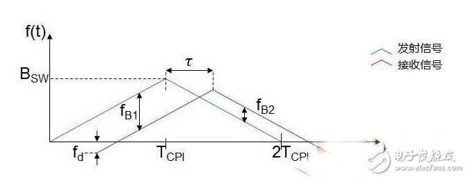
The LFMCW waveform is as follows. The distance and velocity of a single target are obtained by a set of beat frequencies of rising and falling edges. However, in the case of multiple targets, the difference frequency of N actual targets has N2 combinations, which ultimately results in N2- N false targets.
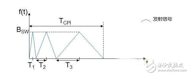
There are many CVS waveforms, the following figure is an example. The transmitter transmits three signals with the same frequency modulation bandwidth and different frequency modulation slopes in TCPI, and the durations are 2T1, 2T2 and 2T3 respectively.
When data processing is performed on the echo signal, the same algorithm as the LFMCW is used for the three segments of signals, and finally three sets of N2 distance-velocity values ​​are obtained. For real targets, the distance-velocity values ​​obtained in the three operations should be the same. For false targets, the distance-velocity values ​​will change with the frequency of the FM period. Therefore, as long as the coincident N distance-velocity values ​​are found from the three sets of results, the distance and speed of the real target can be obtained. Compared with LFMCW, this waveform can remove false targets, and the amount of data processing is also increased, which puts higher requirements on hardware capabilities.
2. Multi-Frequency Shift Keying Radar (MFSK)
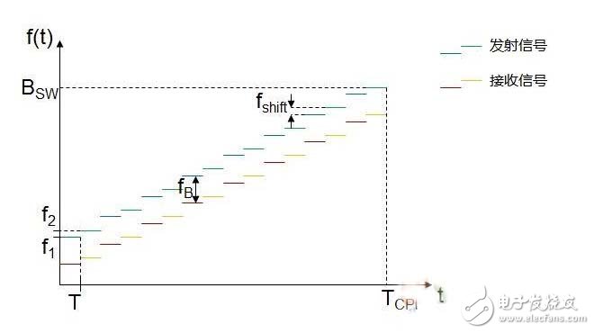
This is a waveform specifically designed for automotive applications that is produced by a combination of linear modulation frequency continuous wave (LFMCW) and frequency shift keying (FSK). As shown in the figure below, the transmitted waveform contains two linear modulations, interleaved step-up signals, sequence 1 is used as a reference signal, and the transmission frequency difference between sequence 2 and sequence 1 is fshift. The received signal is subjected to downmixing to obtain a baseband signal and is sampled on each frequency step.
The baseband signal sequences 1' and 2' are both subjected to the same FFT and CFAR processing. In the case of a single detection target, a target with a specific speed and distance will be detected at the same frequency of the two sequence FFT processing results. Similar to the LFMCW, the difference frequency fB contains both distance and velocity information, but the phase difference between the two signals at the same frequency also includes distance and velocity information. Therefore fB and (symbol 1) need to be used simultaneously to resolve the distance and velocity during a measurement period.
In this case, false targets can be completely avoided. Compared with LFMCW, MFSK introduces phase difference information when calculating distance and speed. When the system design can only achieve lower signal-to-noise ratio, its accuracy will decrease.
3. Fast ramp sequence radar
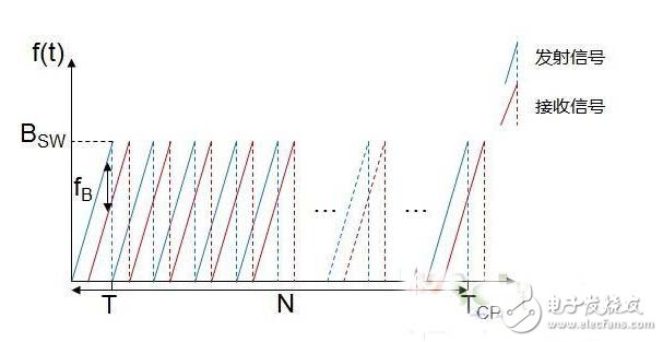
The transmitter continuously emits N sawtooth waves with a large slope in time TCPI, each of which has a duration of T. Since each sawtooth wave has a large slope and a short duration, the beat frequency fB is mainly determined by the change of the radar signal transmission time, that is, fτ. In this case, the Doppler shift fd can be approximately ignored, that is, fB = fd + fτ ≈ fτ.
In signal processing, the beat frequency fB detected after the FFT (one-dimensional FFT) of the sample point sequence in each sawtooth wave can be directly used to estimate the distance. For the measurement of the relative velocity, all the sawtooth waves transmitted in the entire TCPI are required to participate together to reflect the envelope variation of the echo signal. The one-dimensional FFT result of all sawtooth waves is further FFT (two-dimensional FFT) in another dimension to obtain the Doppler frequency shift fd and then obtain the relative velocity, and the relative velocity can further correct the one-dimensional FFT pair distance. Calculation results.
This waveform and subsequent processing algorithms solve the distance and relative speed more directly and accurately. At the same time, the two-dimensional FFT can further improve the signal-to-noise ratio of the signal and lay a good foundation for the subsequent detection algorithm. At the same time, the short single sawtooth duration requires a faster transmit modulation control circuit, a higher baseband sampling rate, and a two-dimensional FFT algorithm that requires more processor power, which places higher demands on the hardware.
It can be seen from the above three commonly used frequency modulation systems that different systems have advantages and disadvantages in terms of ranging and speed measurement performance, and the requirements for hardware capabilities are also different. Radar system designers need to carefully measure the selected system and the corresponding hardware and software architecture at the outset in order to achieve the expected system performance in the later stages.
ADI's radar modulation phase-locked loop chip ADF4158/4159 chip can support most mainstream FM systems, including the above-mentioned CVS, MFSK, FRCS, and conventional LFMCW, FSK, CW, Parabolic and so on. Its bandwidth, period, FM steps, step frequency, FM slope and waveform, FSK, delay and other parameters can be easily configured. Combined with the MMIC chip ADF5901 and ADF5904, designers can design and verify a variety of hardware architectures. FM system and baseband algorithm. More importantly, the ADF415x-based solution can achieve more complex waveforms, easier control, and faster sweeps (up to tens of uS ramp sequences) than with a processor or DAC to control the FM. More precise frequency control to meet the high-end signal processing requirements of the back end.
The ADF5901 and ADF5904 are ADI's MMIC chips for 24GHz vehicle radar. Their functions and specifications are designed according to the vehicle's 24GHz radar. The ADF5904 achieves the industry's best signal detection sensitivity. Based on the vehicle's detection range of more than 300 meters at rated transmission power, the ADF5904 is the first to enable 24GHz-based ACC adaptive cruise or FCW+ACC dual-mode radar. may.
Relative to the distance and speed, the target azimuth angle is mainly measured based on the phase difference caused by the time difference of the echo signals reaching different antennas. The more the number of receiving antennas, the higher the resolution of the angle measurement, but the increase in the number of receiving antennas increases the board area. With the application of MIMO technology in automotive radar, the relationship between different transmitting antennas can be used to simulate more receiving antenna channels without causing a significant increase in board area, which requires MMIC chips to have multiple transmissions. Ability. The ADF5901 and ADF5904 support 2 transmit and 4 receive channels. The two transmit channels can connect two transmit antennas of different FOVs to achieve dual-mode coverage, or connect two identical transmit antennas to implement MIMO function, which is equivalent to one transmit and eight receive. effect. With the development of digital spatial filtering technology, digital beamforming (DBF) technology can further improve the accuracy of angle measurement. Similarly, DBF requires more data operations and requires more hardware capabilities to support it.
ADI's BF70x family of DSPs for this application has a maximum of 400MHz and 1MB of internal SRAM and supports extended DDR2 memory. For FFT operations, the BF70x's two enhanced multipliers can each perform a 32-bit or two-16-bit multiply-accumulate calculation in a single cycle. A large number of optimized mathematical functions and butterfly operators can be solidified in the built-in ROM before leaving the factory, saving a lot of valuable internal instructions and data space. These features help users implement more complex radar algorithms in less computational time.
The ADF5901-ADF5904-ADF415x-BF70x form a set of 24GHz vehicle radar solutions with excellent hardware performance and software scalability to meet the requirements of the mainstream FM system and baseband algorithms discussed above for radar hardware architecture and data processing capabilities.
Lightning Cable is one of our most important products , which is used to connect Apple mobile devices . It contains Short Lightning Cable , long lightning cable , Braided Lightning Cable , leather lightning cable , etc .
Lightning cable fit for iPhone iPad and iPod , With lightning connector to your computers USB port for syncing and charging Connects the USB power adapter for convenient charging from a wall outlet .
Color : black , white , red , gold , gray , blue , silver , pink .
Length : 1.5ft , 3ft , 6ft , 10ft , etc .
Type : 8 pins lightning to USB charger cable .
We focus on independent research and innovation, providing more durable , cheap , high quality , cool lightning cable to our customers . it hits all the right notes in terms of design, functionality, and price. It`s impossible for us to test every Lightning cable, but having tested hundreds of them since Apple replaced the 30-pin connector in 2012, and after comparing the PowerLine cable against our previous top picks, we can say that MaiMi cable stands out from the crowd.
Lightning Cable
Lightning Cable,Short Lightning Cable, Braided Lightning Cable,Iphone Lightning Cable
Hebei Baisiwei Import&Export Trade Co., LTD. , https://www.baisiweicable.com