GSR real-time signal monitoring system based on VB
With the rapid development of information technology, all kinds of giant medical equipment are also developing in the direction of miniaturization and embedded, and the networking of medical monitoring information has become a trend.
The skin galvanic response monitoring system developed in this paper is a set of GSR monitoring system based on C8051 single chip. This monitoring system combines the computer PC and the GSR lower computer to complement the two advantages, and can make full use of the personal computer's powerful human-machine interface functions, rich application software, and low prices to form a high-performance PC-GSR monitoring Management system. Using the MSComm communication control under VB to realize the communication between GSR and PC, a GSR real-time signal monitoring system based on VB was developed.
1 Hardware part
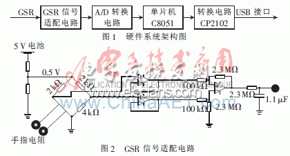
The hardware part of the system includes GSR signal adaptation circuit, analog-to-digital conversion, single-chip microcomputer, serial output level conversion and other parts. The principle block diagram is shown in Figure 1. After the output signal of the PC-GSR monitoring system is converted by the GSR signal adaptation circuit, the A / D conversion circuit performs A / D sampling at a fixed rate under the control of the microcontroller (C8051), and the result is sent to the microcontroller, and the microcontroller then sends the data Send to computer PC through serial port. The GSR signal adaptation circuit is shown in Figure 2.

1.1 Analog-to-digital conversion
To transfer GSR signals through the serial port, you must first convert the GSR analog quantity into a digital quantity. In the design, TI's 8-bit analog-to-digital conversion integrated circuit TLC0820 is used. Using read mode, the read mode timing diagram is shown in Figure 3. The CS and RD signals of TLC0820 are connected to the output ports P2.0 and P2.1 of the microcontroller, and D0 ~ D7 are connected to the P0 port of the microcontroller.

1.2 Microcontroller
In this design, the microcontroller uses C8051, where P0 port is used to read in data, and P2.0 and P2.1 are used to control the start and end of analog-to-digital conversion. P2.2 drives an LED through a triode to indicate whether to enter the continuous sampling state. The serial port is used for data output. The output data is connected to the serial port of the PC after level conversion.
1.3 CP2102
The interface between the lower computer GSR and the upper computer PC is a serial port. Since the serial port on the PC is not commonly used, the CP2102 chip is used for USB-UART conversion [2]. The chip supports all handshake, modem interface signals, baud The rate can be from 300 b / s to 1 Mb / s, and finally an extra COM port is virtualized on the PC, so that the USB can be used as a serial port. Its external circuit diagram is shown in Figure 4.

Magnetic Bluetooth Earphone,Running Wireless Earphone,Earphones With Bluetooth,Wireless Earphone
Dongguan Fangbei Electronic Co.,Ltd , https://www.connectorfb.com