JPEG2000 compression and transmission system based on LM9627
Abstract: This system uses National Semiconductor ’s high-speed color image sensor LM9627, multi-chip floating-point DSP TMS320C6713 as the image processing hardware platform, and 400,000-800 gate FPGA as the image acquisition controller to achieve high quality and high compression Ratio, low bit rate JPEG2000 encoding, through the Bluetooth wireless transmission protocol to transmit the data stream to the host computer for display and storage.
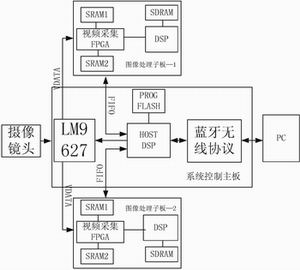
Figure 1 System hardware block diagram
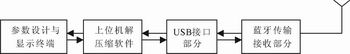
Figure 2 Base station design
System structure The whole system is mainly composed of n PC base stations and m & TImes; n handheld mobile terminals (each PC base station is responsible for m handheld mobile terminals). Among them, the PC base station uses USB2.0 as the core, and realizes high-speed communication between the handheld mobile terminal and the base station through the Bluetooth wireless transmission protocol. Hand-held mobile terminals use TMS320VC5402 as the core to achieve system control, and TMS320C6713 as the processor to implement the JPEG2000 image coding algorithm.
System hardware design Hardware structure As shown in Figure 1, the entire system uses a stack structure similar to PC104, which is mainly composed of LM9627 camera, image processing daughter board and system control motherboard.
LM9627 module design In order to improve the scalability of the system, this system takes the camera as a single module design, which mainly includes three parts: analog part, data interface and control interface. Among them, J2 is the data interface, which is connected to the FPGA of the image processing daughter board; J1 is the control interface, which is connected to the system control motherboard.
Image processing daughter board The image processing daughter board is composed of the acquisition and control coprocessor FPGA, C6713, and two "Ping Pong" working SRAMs.
Two video capture FPGA chips EP1C6Q240 capture odd and even frames (each frame contains odd and even fields) images, each FPGA performs format analysis on the LM9627 video stream, converts the corresponding RGB components to YUV components, and The 4: 1: 1 format is stored in SRAM. The two SRAMs work in a "ping-pong" manner, that is, one slice is used to capture video images at the same time, and the other slice is used as a DSP image buffer.
Two C6713 implement complex JPEG2000 compression algorithm. For subsequent expansion, the C6713 can process larger-sized images. Each DSP expands 16MB of SDRAM. The SDRAM works at a frequency of 100MHz to meet the requirements of large amounts of data exchange during image compression.
System control motherboard The system control motherboard uses DSP C5402 as the core processor and is mainly responsible for three tasks: by controlling the LM9627 camera; allowing multiple image processing daughter boards to coordinate their work, and reading their compression results through MailBox-FIFO; The compression result is sent to the PC base station according to the Bluetooth protocol.
In order to meet the high data exchange speed, the main processor TMS320VC5402 works at 100MHz. While reading the compression result through MailBox-FIFO, the read compression result is sent to the PC base station according to the Bluetooth protocol, thereby realizing real-time compression and decoding display of JPEG2000 .
System software design Image acquisition software design In order to make the system real-time, it can work through the LM9627's I2C control bus to work in interlaced scanning mode, then output 640 & TImes; 480 resolution image data. And the field frequency is: frame rate
(Interlace), line frequency.
This article uses Verilog HDL language to realize the real-time image acquisition of LM9627.
JPEG2000 algorithm design on C6713 The development of JPEG2000 encoding algorithm of this system on C6713 includes two stages.
The first phase of algorithm implementation uses C language to simulate DSP's JPEG2000 algorithm to judge the correctness of the code, verify the complexity and reliability of the JPEG2000 algorithm, and JPEG2000's own compression performance.
The JPEG2000 encoder of this system includes three main modules: wavelet transform, entropy encoding (MQenc), code rate control and packing (rateallocaTIon). The output of LM9627 is RGB, which is converted into a video data stream of Y: U: V = 4: 1: 1, and DC displacement, wavelet transform, and entropy coding are performed on the three components, and then all code blocks of the three components are encoded The stream is hierarchically organized according to the code rate control requirements, including the code stream truncation operation, and the output of the encoder is the packed layered bit stream.
The purpose of performing DC level shifting (preprocessing) is to be able to correctly recover reconstructed unsigned sample values ​​from signed values ​​during decoding. The traditional wavelet transform is quite computationally intensive, and often transforms 8-bit image data into floating-point type, which introduces quantization distortion in the encoding, which is not conducive to lossless compression of image data. Therefore, JPEG2000 mainly uses UMDFB (pull 2 ​​to 1 filter) Group) Lifting wavelet algorithm. Its advantages are fast speed, low operation complexity, less storage space required, and the obtained wavelet coefficients are the same as those obtained by using traditional wavelet transform. JPEG2000 selects two filters: LeGall5 / 3 filter and Daubechies9 / 7 filter. Considering the real-time requirements and lossless compression requirements of this system, 5/3 wavelet calculation is selected. When the wavelet decomposition level is increased, the energy of the decomposition coefficient is more concentrated, but the increase of the wavelet decomposition level will reduce the coding efficiency. For this system, 4CIF (704 & TImes; 576) resolution sampled image is subjected to 5 level wavelet decomposition , CIF (352 × 288) image 4-level wavelet decomposition is sufficient. Due to the integer mode operation, all quantization steps are set to 1, that is, the quantization process can be ignored.
Multi-resolution support can be realized by wavelet transform, and multi-distortion support can be solved by entropy coding. Traditional Huffman coding adopts entropy coding for each coefficient in turn; JPEG2000 coding system divides the wavelet-transformed subband into small code blocks, and organizes the wavelet coefficients in the code block into several bit planes for coding. Using the "bit plane" as the coding element has two advantages: it can make better use of the local statistical characteristics of the image and provide support for randomly acquiring the image compression bit stream; it helps to improve the error resistance performance of the compressed code stream. When performing block encoding, JPEG2000 emphasizes the support of multiple truncation points. The more truncation points, the more the image can provide quality options. If only bit plane coding is performed for each code block, then for a block with the highest number of data bits being N, at most N truncation points can be obtained. Many times the cutoff is rough and the number of cutoff points is too small. In order to obtain more truncation points, EBCOT introduces the concept of "encoding channel", and further divides each bit plane into sub-bit planes (encoding channels). Three coding channels are used in the JPEG2000 coding system: validity channel, amplitude thinning channel and clear channel. In this way, for a certain code block Bi, there may be 3N possible truncation points. When performing bit-plane coding, JPEG2000 uses fast adaptive binary arithmetic coding.
The second phase of the algorithm is to compile JPEG2000 assembly code, and extract code segments that have a greater impact on performance for further optimization. TMS320C67l3 is based on TI's VLIW technology, and the VLIW structure design program can take full advantage of the parallel work of multiple functional units of DSP. Each channel of DSP has four functional units (L, S, M, D), and each functional unit is responsible for completing certain logical or arithmetic operations. In addition, the mutual access of the two channels of A and B can be through the cross unit 1x, 2x done. Most instructions of TM320C6713 can be completed in a single cycle, and can directly operate on 8/16 / 32-bit data. At the same time, it can have up to 8 instructions executed in parallel; all instructions can be executed conditionally. All the above features improve the execution efficiency of instructions, reduce the code length, and improve the coding efficiency.
C6713 has only two D units responsible for data access. In a clock cycle, at most two data access instructions are executed in parallel, and the LDB / LDH / LDW instructions that fetch data from the storage area have a delay of 4 clock cycles. Affect the efficiency of the CPU. For this reason, the number of times to fetch data from the storage area should be minimized when coding. For example, in the wavelet transform, when we take the 8-bit sampled data in the SRAM (LDB), we can make full use of the C6713 32-bit register, and take the 4 adjacent 8-bit numbers from the storage area at a time ( Use 32-bit operation instructions (LDW), and then perform calculations separately, so that the CPU resources are fully utilized and the data access amount is reduced by 4 times.
Pipeline operation is one of the key technologies for DSP to achieve high speed and high efficiency. When the processing of an instruction is ready to the next level of the pipeline, but the level is not yet ready to receive new input, pipeline conflicts are inevitable. Pipeline conflicts can be divided into three categories: jump conflicts, register conflicts, and memory conflicts. In order to solve the problem of pipeline conflicts, special attention should be paid to the delay of C6000 instructions when using assembly language. Some instructions are not immediately available.
In addition, in order to ensure code efficiency, it is necessary to know the number of operating cycles of each instruction in advance, and arrange the instruction in advance or readjust the order of instructions. Only by placing the instructions before and after these instructions in parallel within their required delay gaps can we achieve the effect of reducing wait cycles and improving program efficiency. After the C language simulation algorithm is optimized to the full assembly, and then the assembly code is optimized, the performance of the system is greatly improved.
Base station design
The PC base station is mainly composed of two parts: Bluetooth receiving and host computer JPEG2000 decoding. Its principle is shown in Figure 2. The decompression software of the host computer mainly includes the LM9627 sensor setting and image acquisition control. The former mainly sends the slave address and setting value to the terminal, and the terminal sets the LM9627; the latter controls the image acquisition resolution and compression ratio of the system.
Test results Comparison of subjective image quality Due to the adoption of the above technology, in theory JPEG2000 should provide better performance and more functions, the following through several sets of comparative data to verify. The JPEG algorithm used as a reference is the most widely used compression algorithm on the current hardware platform in the industry. The test picture is a 24-bit true-color lenna image. The compression performance metric used in the experiment is the peak signal-to-noise ratio (PSNR):
PSNR reflects the statistical average of image signal-to-noise ratio changes, and it is a widely used method to measure the subjective quality of images. From the data in Table 1, the following conclusions can be drawn: at higher compression ratios, the signal-to-noise ratio of JPEG2000 is 6-9dB higher than that of JPEG; at high resolution, the signal-to-noise ratio of JPEG2000 is lower than the code The rate of decline, which means that the higher the resolution, the more it can reflect the high compression ratio performance of JPEG2000. When the signal-to-noise ratio is lower than 26dB, the reconstructed image of JPEG can no longer be distinguished due to the severe mosaic effect. At this time, although the reconstructed image of JPEG2000 has lost some details, the outline of the image is still clear. "-" In the table indicates that the image quality is already very low at this time, and the calculated PSNR value is no longer meaningful.
System processing speed This system allows two image processing daughter boards to work stably and reliably in parallel under the control of the system control board DSP-VC5402. The specific test results are shown in Table 2.
Conclusion This system has realized high-quality image compression function at low cost, and has wide application value. The main application areas can be roughly divided into two parts: one is the traditional JPEG market, such as printers, scanners, and digital cameras, and the other is an emerging application area, such as network transmission, wireless communication, and medical images.
Since earlier Motion JPEG did not provide lossless mode, it could not be widely used in the field of video coding. The JPEG2000 algorithm used in this system combined with the high-efficiency processing performance of the DSP system can well introduce the static image compression technology into the field of video coding.
Xinxiang Mina Import & Export Co., Ltd. , https://www.mina-motor.cn