Discussion on RS-485 communication between Mitsubishi PLC and Mitsubishi inverter - News - Global IC Trade Starts Here Free Join
In modern industrial automation systems, the integration of PLCs and frequency inverters is a widely used approach. Traditionally, the PLC’s output contacts are used to drive intermediate relays that control the start, stop, or multi-speed operation of the inverter. However, more advanced methods involve using a D/A expansion module with the PLC to provide continuous control over the inverter's operation and synchronization between multiple units.
For large-scale production lines, where many inverters are involved and motor distances vary, traditional analog signal-based control can lead to signal fluctuations and inconsistent attenuation due to long cable runs. This results in reduced system stability and reliability. Using RS-485 communication offers a more efficient solution. It allows for single-cable control of multiple inverters, enabling synchronized operation with lower costs, longer transmission distances, and better noise immunity.
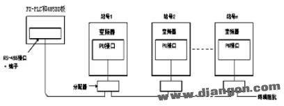
Figure 1: System hardware components
The main components of the system include:
- FX2N-32MT-001 – The central processing unit of the system.
- FX2N-485-BD – A communication adapter for the FX2N series PLC, used to exchange data with the inverter.
- SC09 cable – Used for connecting the PLC to a computer for programming and monitoring.
- Five-core communication cable – Designed for RS-485 data transfer between the PLC and the inverter.
To set up the communication, one end of the five-core cable is connected to the FX2N-485BD, while the other end is attached to the PU port of the inverter via a dedicated connector. The terminal block definition for the inverter’s PU interface is shown in Figure 2.
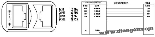
Figure 2: Inverter interface terminal block definition | Figure 3: Communication connection between PLC and inverter
Before communication can occur, the inverter must be initialized with the correct communication settings. If these settings are not properly configured, data exchange will fail. After each parameter adjustment, the inverter must be reset to apply the new settings. Once set, the communication follows a defined protocol as illustrated in Figure 4.
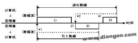
Figure 4: RS485 communication protocol diagram
The communication protocol includes:
- 1. Data request from the PLC to the inverter
- 2. Response data from the inverter when writing data
- 3. Response data from the inverter when reading data
- 4. Data sent from the PLC to the inverter during read operations
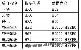
The data is transmitted in ASCII format (hexadecimal). Each instruction code defines specific data types, such as frequency settings or parameter ranges.
Software design plays a crucial role in implementing this communication. The PLC program must initialize the FX2N-485BD, process control commands, convert codes, and handle inverter responses. A typical flowchart of the PLC communication program is shown in Figure 5.
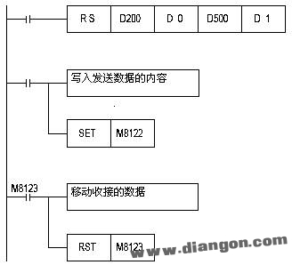
Figure 5: PLC communication flow chart
An example of a PLC program for controlling the inverter through RS-485 communication is provided below in instruction list format:
0 LD M8002
1 MOV H0C96 D8120
6 LD X001
7 RS D10 D26 D30 D49
16 LD M8000
17 OUT M8161
19 LD X001
20 MOV H5 D10
25 MOV H30 D11
30 MOV H31 D12
35 MOV H46 D13
40 MOV H41 D14
45 MOV H31 D15
50 MPS
51 ANI X003
52 MOV H30 D16
57 MPP
58 ANI X003
59 MOV H34 D17
64 LDP X002
66 CCD D11 D28 K7
73 ASCI D28 D18 K2
80 MOV K10 D26
85 MOV K0 D49
90 SET M8122
92 END
When this program runs, the PLC communicates with the inverter via RS-485, and the inverter can be started or stopped using the X3 input. Control instructions are detailed in the following image.
In conclusion, this article demonstrates how to use RS-485 communication with Mitsubishi PLCs and their inverters. It provides practical examples to help readers understand and implement the system. Integration with Mitsubishi F900 series touchscreens enhances flexibility and application scope.
N-Type Solar Panel,Mono Solar Pv Panels,Home Made Solar Panel System,Bifacial Solar Panels
JIANGSU BEST ENERGY CO.,LTD , https://www.bestenergy-group.com