Introduction to six basic audio measurement projects
In audio testing, most tests involve six basic test items for audio, namely:
Level frequency response total harmonic distortion plus noise phase crosstalk SNR
The audio test is basically based on the excitation response. The excitation signal of the known characteristic is added to the input end of the test object, and the signal characteristic of the output end of the test object is measured, thereby comparing with the signal of the input end, and measuring The signal degradation at the output is used to judge the audio performance of the test item. Of course, the excitation signal can be directly output through an audio analyzer (such as the US AP, domestic ABTEC A2, etc.), or can be tested by playing a standard test signal directly on the test object.
In audio testing, the most common excitation signal is a sine wave signal, because this signal can concentrate energy at a point in the spectrum, so the comparison test is relatively simple. In daily tests, multiple sine waves or noise are also used for testing.
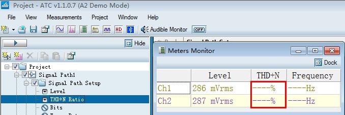
1. Level test:
Level testing is the most basic and simpletest test in audio testing. In this test, you may need to test the output level, power, gain, etc. When testing, the level of the maximum undistorted (1%) is generally tested. In the test, the output of the product to be tested is connected to the load (according to the actual needs of the product to receive the corresponding load), and then the signal at both ends of the load is measured, the volume of the product to be tested is adjusted to the maximum, and then the signal amplitude is adjusted, and the signal is real-time on the instrument. Look at the magnitude of the signal distortion. When the distortion is 1%, this signal is the maximum undistorted signal. In the subsequent tests, the input level under this specific distortion is generally used as the excitation signal source. The general test signal Frequency is 1 kHz:
The gain is different in different products to be tested. If some products have the function of volume or tone adjustment, the gain of these products can be adjusted, so when testing, set the gain control as needed.
In the test, the gain of the test object is calculated based on the output level and the input level. Therefore, when testing the gain, it is necessary to use a so-called closed-loop test, that is, the excitation signal is provided by the instrument output, and the output level of the product is input to the audio analyzer for real-time analysis. This test is fast and accurate, and automated testing is easier to implement.
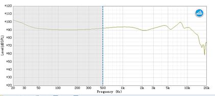
2. Frequency response
The frequency response refers to the output signal level when the test object is excited by an excitation signal of a different frequency of a known level. The most common method is to scan the sine wave signal from the lowest frequency to the highest frequency within the frequency range of the product to be tested, and draw the result at the same level.
In the sweep test test, the scan level is first determined. It can be scanned at low level, but noise or other spurious signals may appear in the response; it can also be scanned at a high level, but high distortion may occur.
Power amplifiers typically use an input level of 1W output. The acoustic response test method is similar, but the unit is generally dBSPL.
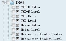
3. Total harmonic distortion plus noise THD+N
The full name of THD+N is called total harmonic distortion plus noise, and harmonic distortion refers to the unnecessary extra tone added by the original audio signal. It is the harmonic related tone of the original signal. When the signal is a sine wave of frequency f1, the harmonics are f2, f3, etc., which are integer multiples of the original pitch. The total harmonic distortion is the sum of all the harmonics in the bandwidth of the device under test.
It has always been tested with total harmonic distortion plus noise. Some people ask why the harmonics and noise are not tested separately, because the Fast Fourier (FFT) test is used when performing the total harmonic plus noise test. It is difficult to separate harmonics from noise, but it is relatively simple to add together. Of course, the current new audio analyzer (ABTEC's A2) has been able to view the total harmonics, noise and distribution of harmonic signals from f2-f10 in real time as needed.
Because the total harmonic distortion plus noise is closely related to the test bandwidth, the wider the bandwidth, the more noise and harmonic components are included, so pay attention to the bandwidth setting when testing.
The other is to test the input level setting. At low level, the output signal is small, but the noise of the test item is relatively high in the output level; at high level, the topping distortion may occur. Therefore, the total harmonic distortion will be relatively high, so the maximum input level of 1% without distortion is generally tested.
Phase
In audio testing, phase measurements are used to describe the time offset in the periodic waveform cycle, which is measured from the reference waveform. The reference value is usually the same signal at different points in the system or related signals located in different channels. The choice of reference value defines two common phase measurements: input and output phase and channel-to-channel phase. The unit of phase is ° degree.
The phase test also provides a specified level, tested at one frequency or different frequencies, either at the phase of a single point frequency or at a phase in the frequency range.
When testing the phase of the input and output channels, select one of the channels of the instrument as the reference channel and connect directly with the connecting line, because the delay of the signal transmitted in the relatively short test line is basically negligible, and the test channel is referenced by the reference channel. The point calculates the phase change.
Phase test between channels, select one of the channels as the reference channel, the phase difference between the test channel and the reference channel is the test result we need.
5. Crosstalk
In an audio system with more than one channel, it is a problem if a signal of one of the channels appears at a lower level signal at the output of the other channel. This cross-channel signal leakage is called crosstalk. Crosstalk is expressed as the ratio of the unwanted signal in the unexcited channel to the signal in the excited channel. Crosstalk is largely caused by parasitic capacitance and inductive coupling between the channel conductors in the device, often with increasing frequency.
If the circuit impedance is approximately a frequency-independent constant, the crosstalk caused by a single capacitive coupling will increase with a frequency increase of 6 db/oct. Due to inductive coupling, shared power, and common ground loops can also cause crosstalk.
6. Signal to noise ratio
How much noise is too big? It depends on the loudness of the signal.
The signal-to-noise ratio SNR is a measure of this difference. The signal is typically set to the nominal operating voltage or the maximum operating level of the device under test. When using the maximum operating voltage for the signal-to-noise ratio test, the measurement can be called the dynamic range because it shows the two level extremes in the device under test. It should be noted here that the dynamic range in the digital domain is different in meaning. The signal to noise ratio is usually expressed in decibels.
The measurement of noise must be the specified measurement bandwidth and weighting filter.
In the process of testing the signal-to-noise ratio, it is necessary to perform two steps. First, input an excitation level to the test object, the instrument acquires the size of the signal, then turns off the signal, obtains the noise signal, and then performs comparison calculation. The value of the signal to noise ratio. Today's instruments automatically control signals and automatically calculate data.
CAT7 Ethernet Cable known as Category 7 or Cat-7 cable is used to cable the infrastructure of Gigabit Ethernet. CAT7 Network Cable offers up to 600MHz. CAT7 patch cable supports high-speed ethernet communication up to 10 Gbps. These are backward compatible with Cat6, Cat5, and Cat5e categories.
You might be wondering whether it's worth your while to consider CAT 7 cable.
CAT 7 cable, whilst being the more expensive option, is also considered the most durable, and has a longer lifespan than CAT 5 and CAT 6, improving its overall return on investment, and is the best choice for wiring with the future in mind.
")
Cat7 Ethernet Cable,Cat 7 Ethernet Cable Coupler,Cat 7 Ethernet Cable Compatibility,Cat7 Lan Ethernet Cable
Shenzhen Kingwire Electronics Co., Ltd. , https://www.kingwires.com