A simple analog contact switch circuit design
After learning the circuit knowledge for a while, I believe that many of my friends hope to be able to make circuits by themselves. However, due to the limitations of knowledge and experience, overly complex design is not suitable for beginners. Some simpler designs are better choices. This article will introduce you to a simple analog contact switch circuit diagram, interested friends to take a look.
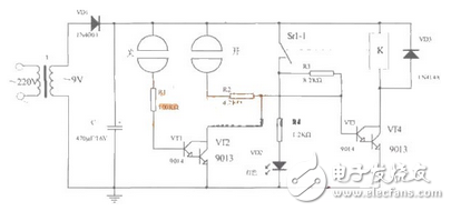
Figure 1 shows a simple analog touch shape circuit that utilizes the characteristics of a transistor switch.
When the power is turned on, VTl-VT4 is in the off state, no current flows through the relay coil, the relay normally open contact is opened, and the light-emitting diode VD2 is not lit. When using the finger to touch the "on" switch, the power supply is passed through the finger resistance (about several hundred to several thousand ohms), R2 is injected into the VT3 base, the composite tubes VT3, VT4 are turned on, the current in the relay coil is passed, and the normally open contact is closed. , VD2 is bright. Since the normally open switch is closed, R3 is connected to the VT3 base circuit, and after the finger leaves the electrode, VT3 and VT4 can still maintain the conduction state. When it needs to be extinguished, you can touch the "off" electrode piece. Since the positive power supply is injected into the VT1 base through the finger resistance and R1, VT1 and VT2 are turned on, and the collector potential of VT1 and VT2 is lowered.
That is, the base potential of VT3 drops, VT3 and VT4 turn from the on state to the off state, no current flows through the relay coil, the normally open contact opens, and VD2 goes out.
The component selection is shown in the table below.
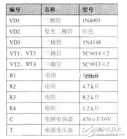
Table 1
Installation, commissioning and testing
1. Install each component according to the assembly drawing.
2. It is better to use a rust-proof metal piece for the finger touch switch electrode.
3. After checking the error, turn on the power.
4. Use the multimeter DC voltage file to measure the voltage across C, which is normally about 9V.
5. Touch the “open†electrode with your finger. The base voltage of VT3 increases from 0 to 1.4V. VT3 and VT4 are turned on, the relay is closed, and VD2 is bright.
6. Touch the “off†electrode with your finger. The VT3 base voltage drops. VT3, VT4 are cut off, the relay is released, and VD2 is extinguished.

figure 2
This article provides a simple and easy-to-use analog touch switch circuit diagram for beginners through the combination of graphics and texts. Interested friends can try to design according to the circuit and related instructions given in the article, while learning new knowledge. Consolidate your own hands-on ability. In detail, everyone will have an unexpected harvest after reading this article.
Glass Door Chiller,Glass Door Freezer,Glass Door Display Freezer,Glass Door Refrigerator Freezer
ZHENGZHOU KAIXUE COLD CHAIN CO., LTD. , https://www.supersnowfreezer.com