At present, most audio signal processors are not only bulky and expensive, but are difficult to popularize in some special aspects. Embedded system analyzers are small and reliable, so the development of audio analysis instruments based on special function microcontrollers is the basis of speech recognition. , Has very good practical significance. The principle of signal analysis is to convert the signal from the time domain to the frequency domain, so that the unobvious characteristics in the original signal become obvious, which is convenient for analysis and processing. For audio signals, the main characteristic parameters are amplitude spectrum and power spectrum. The working process of the audio signal analyzer is: limiting amplification of the audio signal, analog-to-digital conversion, fast Fourier transform (FFT, time domain to frequency domain conversion), feature value extraction; from the amplitude spectrum of the audio signal, In turn, the power spectrum of the audio signal is obtained.
1 Hardware design
"Smart Home" (SmartHome) is also called smart home. The home network intelligent control system is to use advanced computer technology, communication technology and embedded technology to connect various devices in the home through the home network to form a system. The composition of the entire smart home system is shown in Figure 1. In this system, audio signal analysis is required for the monitoring and control of certain household electrical appliances.
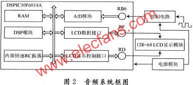
This design uses Microchip's DSPIC30F6014A microcontroller as the core processor. This chip is a combination of MCU technology and DSP technology. It not only contains the control function of 16-bit MCU, but also integrates the high-speed computing technology of DSP, which is actually a digital microprocessor. , Can easily realize various functions of audio signal analysis. The audio system block diagram is shown in Figure 2, including several parts such as power supply module, prefabricated circuit, A / D conversion module, DSP module, LCD display module and so on. The specific design and implementation functions of each module and interface are as follows:
(1) Power supply module: It adopts a DC three-terminal regulated power supply design. After 220 V AC is stepped down, rectified, filtered and stabilized, it is converted into ± 5 V and ± 12 V power supply voltages required by the system.
(2) Prefabricated circuit: In order to ensure that the input bandwidth is in the audio range, the front-end DC bias circuit uses an OP07 amplifier, the first-stage adder adds the input signal to the 2.5 V voltage value, and the second-stage inverter Transfer the signal to the 0 to 5 V range that the A / D conversion can handle. Due to the grounding of the 50 Ω resistor at the input, the system input impedance is approximately 50 Ω.
(3) A / D conversion module: because there is only one input for the audio signal, only AN6 is used in the 16 analog input pins of the 12-bit configurable A / D module. During initialization, this pin is configured as Analog input pin, at the same time, because the processed audio signal voltage is 0 ~ 5 V, the reference voltage of the A / D module is set to 0 V, 5 V. The conversion output rate is up to 200 KSPS.
(4) DSP module: The digital microprocessor is an improved Harvard structure design, which can be analyzed in real time and has a high resolution. The DSP module is called through the MPLAB C30 C compiler of Microchip. The compiler provides 49 DSP processing functions, which can complete all digital signal processing.
(5) LCD display module: used to visually display the spectrum waveform.
(6) ICD2 debugging interface: ICD2 online debugging device of Microchip is selected, for which ICD2 debugging interface is reserved.
(7) RC Oscillator: This MCU can work in four modes: external clock input, external RC input, internal fast RC oscillator, internal low power (RC) oscillator, and post-frequency division used at low power consumption Device. This design uses an internal fast RC oscillator, which can provide a clock of 7.37 MHz, because the real-time processing of audio signals is needed, so no post-divider is used.
2 Software design
The main loop of the audio system is shown in Figure 3.
(1) After sampling and A / D conversion are completed, clear the A / D enable flag to obtain a discrete digital signal.
(2) Call the period judgment function to realize the periodic analysis of the signal.
(3) Call the FFT transform function to implement fast Fourier transform of discrete signals to realize the transform from time domain to frequency domain.
(4) Display the frequency spectrum of the input signal.
(5) Calculate the power spectrum of the signal and calculate the maximum power.
(6) Display the power spectrum and maximum power of the signal.
2. 1 A / D sampling
Theoretical analysis: because of the 12-bit A / D module, the quantization unit is 1/212, because the frequency resolution △ f = 100 Hz, the number of sub-sample points of the FFT N = 512, so the sampling frequency fs = 51 200 Hz (fs≤ N △ f), sampling period Ts = 1/51 200 s (sampling period one sampling time + conversion time). Because the oscillation frequency is 7.37 MHz, the instruction cycle TCY = (1 / 7.37) & TImes; 4 = O. 5μs.
Actual control: The conversion time is 14 TAD (for correct A / D conversion, TAD = 333.33 ns). So, configure A / D automatic sampling time as 6 TADs, A / D conversion clock as 16TCY, then the total time of A / D conversion is 0.092 ms, and the sampling frequency is 10.87 kHz.
The A / D module works in the system clock source, automatic conversion mode, and enters an interrupt every time a conversion is completed. A structure of the number of sampling points should be defined in the program to store the data collected by A / D. Each structure includes a real part and an imaginary part. In the interrupt service subroutine, the digital quantity collected by the A / D module is stored in the real part of the structure, and the sampling points are converted several times. The flow of the interrupt service subroutine is shown in FIG. 4.

2.2 Period judgment
Not only are there many frequency components in the audio signal, but they are not periodic. The measurement period can be in the time domain or the frequency domain, but because the frequency domain measurement periodicity requires certain frequency points to have a regular zero point or near zero point, so for more complex, more frequency components and more uniform power distribution And the low signal cannot analyze its periodicity correctly. Therefore, for the periodic judgment of the signal, the period judgment function should be directly called before the FFT transformation of the signal. The flowchart of the periodic determination subroutine is shown in Figure 5.
2. 3 FFT transformation
Since the calculation amount of the direct Fourier transform is proportional to the square of the number of sub-sample points N, when N is large, the calculation amount is too large, and it is not suitable for implementation in an embedded system with limited resources. Therefore, the most commonly used radix-2 FFT algorithm, the main idea is to decompose the N-point direct Fourier transform into multiple shorter direct Fourier transforms, and then use the periodicity and symmetry of the rotation factor to save to a large extent System resources.
MPLAB C30 C compiler provides almost all the digital signal processing software tools. Through the DSPIC30F series microprocessors, just call the library function provided by Microchip company, you can easily achieve digital signal processing. For the radix-2 FFT transform, the software flow chart is shown in Figure 6.
2.4 Feature value extraction
The quantity that determines the frequency domain analysis includes the sampling frequency and the number of sampling points. Through the FFT transform, the discretized amplitude spectrum X (k) is obtained. The discretized amplitude value is first squared and then divided by the number of sub-sample points N to obtain the power value corresponding to the frequency point (power = X (k) * X (k) / N).
3 Conclusion
The main performance indicators of the system are: input impedance 50 Ω; input signal voltage range (peak-to-peak value) 100 mV ~ 5 V; input signal contains frequency components ranging from 200 Hz to 10 kHz; frequency resolution is 100 Hz (can be measured correctly In the measured signal, the frequency difference is not less than the power value of the frequency component of 100 Hz); the total power of the input signal and the power of each frequency component, the sum of the power of each detected frequency component is not less than 95% of the total power value; The absolute value of the relative error of the power measurement of each frequency component is less than 10%, and the absolute value of the relative error of the total power measurement is less than 5%; the analysis data is refreshed at a period of 5 s, and each frequency component of the signal should be sequentially stored according to the power and can be played back At the same time, the total power of the signal and the frequency value and power value of at least the first two frequency components are displayed in real time, and the pause key is set to maintain the displayed data. The audio signal analysis based on DSP microcontroller technology has the characteristics of stable performance, simple circuit, fast speed, low cost and small size. It is suitable for embedded systems that require audio signal analysis and can be further promoted and applied in more fields, such as environment Monitoring, voice recognition, intelligent system control, etc.
Parking Lamp
Led Parking Light,Parking Lot Lamps,Outdoor Led Parking Lot Lights,Commercial Parking Lot Lights
Changxing Fanya Lighting Co.,Ltd , https://www.fyledlights.com


