Design of CS5460A Chip Grid Ammeter
Design of CS5460A Chip Grid Ammeter
OverviewConventional grid current meters generally use pointer type meters, and they all have the disadvantages of small measurement range, poor stability, low accuracy, inaccurate reading and large errors, which have not been adapted to the needs of social development. With the rapid development of intelligent measurement and control technology. The advantages of digital electric meters with single-chip microcomputer as the core have been very obvious. To this end, this article uses a single-chip microcomputer as the main controller of the instrument, and uses Cirrus Logic's energy metering chip to collect data, and gives a design method of a grid current meter with high cost performance, strong anti-interference ability, and high measurement accuracy.
1 Working principle of the system
In industrial production and daily life, accurate and real-time measurement of grid current is essential. This article uses a switching power supply to regulate 220 V AC mains rectifier to an analog and digital +5 V power supply to power the entire meter circuit. Then detect the current signal through the current transformer, and then convert it into a voltage signal, and send it into the single-phase power / electric energy integrated chip CS5460A, at the same time complete the signal sampling, calculation and error correction on-chip. The whole process can be carried out under the control of MCU. The working principle and structural block diagram of the instrument system are shown in Figure 1.
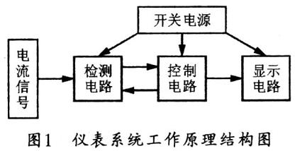
The switching power supply in this system has the advantages of low power consumption, wide voltage range, small size, light weight, safety and reliability. Because the CS5460A is used in the system detection circuit, in order to avoid interference between the modules, the switching power supply part needs to have two +5 V outputs.
2 Current detection circuit based on CS5460A
The current detection circuit in the system is the core part of the ammeter design. Its main function is to detect the current signal and output the instantaneous value to the single-chip microcomputer by the CS5460A under the control of AT89C52. This circuit selects X5045 to store the standard correction value. For the microcontroller to calibrate the current value at any time. The main devices in the detection circuit are current transformer, CS5460A, AT89C52, X5045 and so on.
2. 1 CS5460A function overview
CS5460A is a highly integrated △ ∑ analog-to-digital converter that contains two △ ∑ analog-to-digital converters (ADC), high-speed electrical energy calculation functions and a serial interface. It can accurately measure and calculate active energy, instantaneous power, IRMS and VRMS, and can be used to develop single-phase two-wire or three-wire electricity meters. The CS5460A can use low-cost shunts or current transformers to measure current, and divider resistors or voltage transformers to measure voltage. CS5460A has a two-way serial port for communication with a microcontroller. The pulse output frequency of the chip is proportional to the amount of function. In addition, the CS5460A also has a convenient on-chip AC / DC system calibration function. The "self-booting" feature enables the CS5460A to work independently, and can be initialized automatically after the system is powered on. In self-boot mode, the CS5460A can read calibration data and start commands from an external: EEPROM. When using this mode, the CS5460A does not require an additional microcontroller during operation. Therefore, when the electricity meter is used for large-scale residential energy measurement, the cost of the electricity meter can be reduced.
The CS5460A can provide instantaneous voltage / current, power data sampling, and periodic calculation results of functional quantities, IRMS, and VRMS. In order to adapt to low-cost measurement applications, the CS5460A can also output a pulse train on a given pin, and the number of pulses output is proportional to the value of the functional quantity register. At the same time, CS5460A is also optimized for power measurement, which is very suitable for measuring current by connecting with shunt or current transformer: or measuring voltage by connecting with voltage divider resistance or voltage transformer. In order to adapt to different levels of input voltage, the current channel integrates a gain programmable amplifier (PGA), so that the input level full scale can be selected as ± 250 mVRMS or ± 50 mV RMS. The PGA of the voltage channel can adapt to the input voltage range of ± 250mV. For the case of single + 5V power supply at both ends of VA + and VA-. The common-mode signal voltage added between the differential-mode input pins of the two channels is -0.25 V to +5 V. In addition, the double-ended differential mode input can be realized in one channel or two channels during design. At this time, the common mode voltage of the input signal is added to AGND.
Each channel of CS5460A has a high-speed digital filter, which can attenuate the output of two △ Σ modulators by 10 times and integrate. The filter outputs 24-bit data at a word output rate (OWR) of (MCLK / K) / 1024. To facilitate communication with external microcontrollers, the CS5460A also integrates a simple three-wire serial interface, which is compatible with SPPM and MicrowireTM standards. The serial clock (SCL) of the serial port and a Schmitt trigger included in the RESET pin allow the use of slower rising signals.
The characteristics of CS5460A are as follows:
The linearity of electrical energy data is ± 0.1% in a 1000: 1 dynamic range:
It can measure electrical energy (active power), I * V, IRMS and VRMS on-chip, and has the function of electrical energy to pulse conversion;
It can be "self-booting" intelligently from a serial EEPROM without a microcontroller:
Can be calibrated by AC or DC system:
With mechanical counter / stepper motor driver:
Comply with IEC687 / 1036, JIS industrial standard;
Power consumption <12mW:
With optimized shunt interface:
With V to I phase compensation:
Single power ground reference signal
With 2.5 V reference voltage (maximum temperature drift 60ppm / ℃) on-chip;
There is a simple three-wire string line interface and watchdog timer:
Built-in power monitor:
Power configuration is VA + = + 5 V; VA- = 0V; VD + = + 3.3V ~ + 5 V
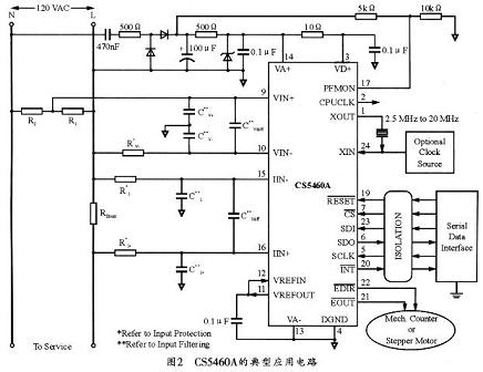
Figure 2 shows the circuit diagram of the CS5460A power measurement solution in a single-power single-phase two-wire system. The circuit can be connected to the live end of the power supply with a resistor shunt that monitors the current of the power supply line.
2.2 Current detection circuit
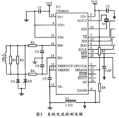
Mutual inductance current of high voltage circuit can be obtained through current transformer. The main advantage of using this form of current transformer is that it can achieve the isolation of high voltage and low voltage. Figure 3 shows the current detection circuit of this system. Since the current detection of the CS5460A is actually a voltage detection after converting the current signal into a voltage signal, the mutual inductance current is converted into a voltage signal by R1 and R2 in the circuit of FIG. 2 and then filtered by R3 and R4 current limiting and C3 and C4 filtering Then input to the current detection pins (16, 15) of CS5460A. In addition, in two inputs. Diodes are also used for voltage clamping to avoid damage to the CS5460A when the voltage is too high. Pins 3 and 14 of the CS5460A are analog and digital +5 V power supplies, respectively. At the same time, in order to filter out voltage fluctuations and increase the stability of the power supply, a small filter capacitor can be added to the two power input terminals. Because this is current detection. Therefore, the two input pins 9, 10 of the voltage detection (in order to avoid interference) should also be connected to the analog ground. In addition, connect the 13-pin VA to the analog ground, and the 4-pin DGND to the digital ground, and connect the analog ground and the digital ground with inductors. 1, 24 (XOUT, XIN) two feet are connected to the crystal oscillator of 4.096 MHz. In order to use the process control CS5460A to automatically complete the detection of the input signal and output data through 6-pin SDO; at the same time, there are 5-pin SCLK, 7-pin CS, 19-pin R \ E \ S \, 20-pin I \ N \ T, 23 pin SDI outputs the clock pulse, chip select signal, reset signal, interrupt signal and control signal of the single chip microcomputer to the CS5460A. Because CS5460A can complete the detection of analog signals and output the detection value with digital signals. That is, a chip has both analog and digital signals of the system current detection circuit in Figure 3. Therefore, it requires two analog and digital power supplies; at the same time. The pins that need to be grounded must be properly connected to the corresponding ground, otherwise it will introduce a lot of interference.
3 Control circuit
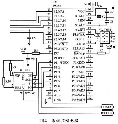
This instrument is controlled by AT89C52 to control the detection process and display value of CS5460A. Its control circuit is shown in Figure 4. After the circuit is powered on, the circuit can be initialized through the DIP switch, and the code of the electric quantity to be initialized by the MCU can be input through the DIP switch. The command sent to the MCU corresponding standard calibration value of the electric quantity to be initialized. After that, the MCU transfers this data to X5045 and stores it in it, so that the calibration value can be obtained again when the CS5460A is reset, and is used by the MCU to calibrate the detection value at any time. This method can greatly improve the accuracy.
4 Display circuit
The instrument system uses seven-segment LED display. The clock signal of the shift register 74HCl64 is provided by the 2-pin P1.1 / T2EX of the single-chip microcomputer, and the data signal is output from the P1.3 pin of the single-chip microcomputer (output low bit first, then output high bit). The data is first transmitted to the 74HCl64 corresponding to the display high nixie tube. Whenever a clock pulse arrives, the data is shifted once. In this way, after a period of time, the data can be completely transmitted to the 74HCl64 corresponding to each bit. Save and display.
5 Software design
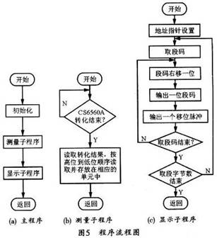
The software design of the grid current meter based on CS5460A is mainly the design of system initialization, measurement subroutine and display subroutine. Figure 5 shows the software flow chart of several subroutines.
6 Conclusion
This paper presents a design scheme of a new civilian ammeter, explains the working principle and design idea of ​​the ammeter in detail, focuses on the principle and implementation circuit of the current detection circuit, and gives the program design flow chart. It has been proved by use that the ammeter has the advantages of good reliability, low cost, high precision and strong practicability. In addition, lightning protection measures can be further enhanced in response to the needs of different users.
Yuhai piezo materials include : hard piezo material, soft piezo material and lead free piezo material
Soft piezo material exhibits: larger piezoelectric constants, higher permittivity, larger dielectric constants, higher dielectric losses, larger electromechanical coupling factors, low mechanical quality factors, a lower coercive field, poor linearity, and is easier to depolarize. The ideal application of soft piezo materials is sensing needs. Yuhai soft pizeo materials are PZT-5, PZT-5H, PSnN-5 and PLiS-51.
Hard piezo material exhibits: smaller piezoelectric constants, lower permittivity, smaller dielectric constants, lower dielectric losses, smaller electromechanical coupling factors, high mechanical quality factors, a higher coercive field, better linearity, and is harder to depolarize. The ideal application of hard piezo materials is high power transducer needs. Yuhai hard pizeo materials are PZT-4, PZT-8, PCrN-4 and PBaS-4.
Yuhai company developped lead free piezo material BaTiO3 and apply for the Chinese Patent in 2011, to meet the needs of environmental protection in today's society.
Piezoelectric Ceramic material
Properties and Classification
General description of material properties
Material Code
Properties
Application
Soft PZT ceramic
PZT-51
Characteristics:
larger piezoelectric constants, higher permittivity, larger dielectric
constants, higher dielectric losses, larger electromechanical coupling
factors, low mechanical quality factors, a lower coercive field, poor
linearity, and is easier to depolarize.
low-power ultrasonic transducers
PZT-52
low-frequency sound transducers
PZT-53
applications with high g coefficient, for example,
PZT-5H
microphones,vibration pickups with preamplifier
PLiS-51
low-frequency vibration measurements
PMgN-51
Hydrophones, transducers in medical diagnostics
PSnN-5
Actuators
Hard PZT ceramic
PZT-41
Characteristics: smaller
piezoelectric constants, lower permittivity, smaller dielectric
constants, lower dielectric losses, smaller electromechanical coupling
factors, high mechanical quality factors, a higher coercive field,
better linearity, and is harder to depolarize.
PZT-42
High-power acoustic applications
PZT-43
Hydroacoustics, sonar technology
PZT-82
piezomotor
PCrN-4
PBaS-4
Lead free Piezo Ceramic
BaTiO3
Characteristics: Low density, low curie temperature, lead free.
Ultrasonic transducers suitable for low-temperature underwater, for example Ultrasonic Transducer in fishfinder
Piezoelectric Material,Piezo Ceramic Element,Piezo Electric Cylinder ,Piezo Sphere
Zibo Yuhai Electronic Ceramic Co., Ltd. , https://www.yhpiezo.com