Application of single-chip WiMAXCPE transceiver in microcell
Recently, some new devices have greatly improved the transmission signal-to-noise ratio (SNR) performance and are therefore suitable for applications ranging from femtocells to microcells .
Base station cellular type and typical requirements
According to the maximum output power and coverage, the wireless industry divides base stations into broad and overlapping categories, as shown in Table 1. The design example below will use power output estimates. Price and device size are very important for all types of cellular. For femtocell base stations, only low-cost and small-size models can survive in the market; for femtocell and macrocell base stations, if their price and size are better than competitive products, they will have unique market advantages. Single-chip transceivers help reduce the price and size, but these advantages can only be seen when the base station meets its performance requirements.

Transmit signal chain architecture
Figure 1 shows a simplified block diagram of a typical direct up-conversion transmit signal path for wireless communications, where the virtual box portion has recently been integrated into a WiMAX CPE transceiver. Base station transmitters, especially those designed for larger cells, often use discrete devices to achieve high linearity and low noise.
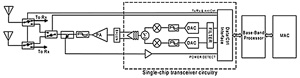
Figure 1 Block diagram of the transmit signal chain
However, as shown in Figure 1, single-chip transceivers have significant cost and space advantages. These CPE transceivers combine multiple functional modules, including digital interfaces, data converters, analog filters, gain stages, mixers, and pre-drivers, to form a mixed-signal integrated circuit. The integration of the data converter and digital interface allows the baseband processor (BBP) to be purely digital, enabling the use of advanced thin-line CMOS processes to reduce cost, power consumption, and size. Some integrated transceivers also integrate two direct down-conversion receivers, further reducing overall space and cost.
Transmit power and noise
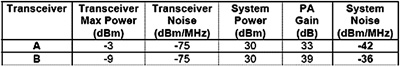
For a specific application, when comparing a transceiver to a discrete design, transmitter noise is a key parameter, but noise is only considered on the one hand. Noise must be measured relative to a specific output power, because the required PA gain is determined by the transceiver output power. For example, if the noise of transceiver B is a few dB lower than that of transceiver A, but requires a few more dB of gain to achieve the same output power, the additional gain of transceiver B will result in higher system noise. When considering absolute radiation limits, as described in the design examples below, the relationship between noise and gain is particularly important. Table 2 shows this relationship through a quantitative example.
In the design process, the relationship between emission noise and frequency offset will help. After the legal spurious emission limit is converted to dBm / MHz, you can quickly determine whether a transceiver is suitable for a given application. Figure 2 shows the relationship between a multi-input, single-output (MISO) WiMAX / WiBRORF transceiver at a carrier frequency of 2500MHz and a signal bandwidth of 10MHz. Note that the frequency offset is the center frequency of the 1MHz integration bandwidth. Therefore, if the center frequency is 5.5 MHz, the edge frequency of the integration bandwidth is 5 MHz. 5MHz is the channel edge of the 10MHz bandwidth target signal.

Figure 2 Relationship between emission noise and integral bandwidth offset
Although the power output in the 10MHz channel is -3dBm, the radiation in the channel is -13dBm, as shown in Figure 2, because the measurement is the result of integration in the 1MHz range, not the entire 10MHz channel. In Figure 2, the very steep roll-off at the edge of the frequency band is caused by the on-chip interpolated digital filter. Integrating these functions into the transceiver chip can reduce the burden on the BBP, and the data rate between the BBP and the transceiver is halved due to 2x interpolation.
Legal restrictions
Regulators have restrictions on maximum output power, maximum out-of-band (OOB) radiation, and maximum out-of-channel radiation in specific frequency bands. These restrictions depend on the country where the application is located and the frequency band used. This article only focuses on FCC (Federal Communications Commission) limits in the 2.4 to 2.7 GHz range. In the United States, the licensed WiMAX deployment spectrum is 2496 to 2690MHz, and the unlicensed spectrum is the 2.4GHz ISM band (2400 to 2483.5MHz).
FCC uses multiple units and methods to specify maximum power and OOB limits. The following sections list the limits for multiple frequency ranges used by WiMAX base stations. If the limit is expressed in terms of attenuation lower than the in-band output power, then the in-band power and the integrated bandwidth used for spurious emissions measurements must be the same.
Licensed frequency band
From 2496 to 2690MHz, the maximum equivalent isotropic radiated power (EIRP) frequency band power output is 63dBm. The spurious radiation of the base station must be attenuated by at least 43 + 10log (P) dB at the channel edge, where P is the frequency band power output (unit W).
LED street lamp refers to the street lamp made with LED light source, which has the unique advantages of high efficiency, safety, energy saving, environmental protection, long life, fast response speed, high color rendering index, and is of great significance to urban lighting energy saving.
Led Road Light,Led Off Road Lights,Led Roadway Lighting,Cob Led Road Light
Yangzhou Heli Photoelectric Co., Ltd. , https://www.heli-eee.com