Design of Energy-saving Lighting Controller Based on Single Chip Microcomputer
1 system design
1.1 The choice of single chip microcomputer
Solution: MCS-51 microcontroller
The AT89C51 is the most widely used model in the MSC-51 microcontroller. It is now represented by its parameters. The AT89C51 microcontroller integrates the basics necessary for control applications on a limited-size integrated circuit chip. If divided by function, it consists of the following components: microprocessor, data memory, program memory, parallel I/O port, serial port, timer/counter, interrupt system, and special function registers. They are all connected by a single bus on the chip, and the basic structure is still the traditional structure mode of the CPU plus the peripheral chip. However, the control of various functional components is a centralized control method using special function registers. Its internal structure mainly has the following parts:
1) Microprocessor The MCU has an 8-bit microprocessor, which is basically the same as a general-purpose microprocessor. It also includes two parts of the arithmetic unit and the controller. It only adds control-oriented processing functions, which can be processed not only. Data can also be processed by bit variables.
2) The data memory is 128 bytes on-chip, and can be expanded to 64k bytes at the off-chip. It is used to store the working variables of the program during operation, intermediate results of the operation, data temporary storage and buffering, flag bits, etc. Called data storage.
3) Program memory Due to the limitation of integration, on-chip read-only memory generally has a small capacity. If the capacity of the on-chip read-only memory is insufficient, an extended off-chip read-only memory is required, and the off-chip can be expanded up to 64k. byte.
4) The interrupt system has 5 interrupt sources and 2 levels of interrupt priority.
5) There are two 16-bit timer/counters in the timer/counter chip, which have four working modes.
6) Serial port 1 full-duplex serial port with four working modes. It can be used for serial communication, extended parallel I/O port, and even connected to multiple microcontrollers to form a multi-machine system, which makes the MCU more powerful and widely used.
7) 4 parallel 8-bit I/O ports are P1 port, P2 port, P3 port, P4 port
8) There are 21 special function registers for managing, controlling, and monitoring the functions of the on-chip functions. In fact, some control registers and status registers are a RAM area with special functions.
1.2 illumination detection method
Solution 1: Using a photosensor such as a photodiode or a triode to convert the ambient brightness to a corresponding digital level, and then directly access the IO pin of the microcontroller.
Solution 2: Use a photoresistor to convert the ambient brightness into a corresponding voltage value (analog value), and then input a standard digital signal to the MCU through the op amp.
Since the photoresistor is a purely resistive device, the first scheme is adopted.
1.3 Human body sensing method
Scheme 1: Infrared tube is used for testing. The infrared transmitting tube and the infrared receiving tube are respectively installed on both sides of the channel. When the infrared receiving tube does not receive a signal at a certain moment, indicating that there is an obstruction between the two, it can be regarded as having a human body entering.
Solution 2: The integrated circuit BIS0001 is used, which is a sensing signal processing integrated circuit with high performance. It is equipped with a pyroelectric infrared sensor and a small number of external components to form a passive pyroelectric infrared switch, a human body pyroelectric sensor for alarm. It can automatically and quickly open all kinds of incandescent lamps, fluorescent lamps, buzzers, automatic doors, electric fans, dryers and automatic hand basins, etc., especially suitable for enterprises, hotels, shopping malls, warehouses and family aisles, corridors and other sensitive Area, or automatic lighting, lighting, and alarm systems for safe areas.
Solution 3: Because the experimental project requires the use of simulation software, the circuit diagram is simulated, and the simulation results are seen when the defense is made. Under the conditions of the laboratory, it is decided to manually switch the analog human signal (when there is no one, the light is extinguished) .
In summary, it was decided to adopt Option 3.
1.4 Lighting device drive circuit
Option 1, using thyristor control. A thyristor, also known as a thyristor, is a four-layer high power semiconductor device with three PN junctions. It has the characteristics of small size, relatively simple structure and strong function, and is one of the more commonly used semiconductor devices.
Option 2, using relay control. A relay is an automatic control device that changes the output when the input quantity (electricity, magnetism, sound, light, heat) reaches a certain value. It has the advantages of fast action, stable operation, long service life and small volume. Widely used in power protection, automation, motion, remote control, measurement and communication devices. According to the structure, it can be divided into electromagnetic relays, thermal reed relays, solid state relays, reed relays, optical relays and other models.
Due to the consideration of laboratory conditions and software simulation requirements, the use of LEDs to replace the relays and lighting systems in the actual circuit, to achieve simulation and simulation of the system.
2 hardware circuit design and implementation
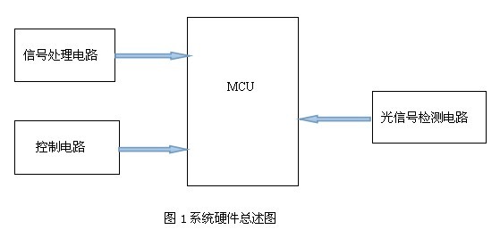
2.1 System Hardware Overview
The system is composed of a single-chip microcomputer and a variety of interface circuits. There are six main parts: AT89C51 chip, optical signal acquisition circuit (photosensitive resistor), human body signal acquisition circuit (using manual switch analog), output control circuit, as shown in the figure. 1 is shown.
2.2 CPU performance introduction
This system uses AT89C51 chip in ATMEL MCS-51 series single-chip microcomputer. It is a low-voltage high-performance CMOS 8-bit microprocessor with 4k bytes of flash flash memory, 128 bytes of internal RAM and 15 I/O ports. Line, two 16-bit timer/counter, a 5-vector two-stage interrupt structure, a full-duplex serial communication port.
2.3 main control circuit design
The main controller adopts AT89C51 single-chip microcomputer as the microprocessor. AT89C51 is a low-voltage, high-performance CMOS 8-bit single-chip microcomputer produced by American ATMEL Company. The chip contains 4K bytes of re-writable Flash read-only program memory and 128 bytes of random memory. Take data memory (RAM), the device is produced by ATMEL's high-density, non-volatile memory technology, compatible with the standard MCS-51 instruction system, built-in general-purpose 8-bit central processing unit (CPU) and flash memory unit.
The peripheral interface circuit of the main controller system is composed of signal processing circuit, LED display and control circuit, and so on.
2.4 pyroelectric sensor and processing circuit
2.4.1 pyroelectric infrared sensor
Pyroelectric infrared sensors detect the infrared radiation emitted by the human body in a non-contact manner and convert it into a voltage signal. Pyroelectric sensors have the characteristics of low cost, no need for infrared or electromagnetic waves, high sensitivity, and flowable installation. In actual use, a Fresnel lens should be installed before the pyroelectric sensor, which can greatly improve the receiving sensitivity and increase the detection distance and range. Experiments show that if the pyroelectric infrared sensor is not equipped with a Fresnel lens, the detection distance is only about 2 m; and with the Fresnel lens, the detection distance can be increased to more than 10 m. Since the signal output from the pyroelectric sensor changes slowly and the amplitude is small (less than 1 mV), it cannot be directly used as the control signal of the illumination system. Therefore, the output signal of the sensor must pass through a special signal processing circuit to make the output signal of the sensor irregular. The waveform is converted into a digital signal suitable for processing by the microcontroller. According to the above requirements, the block diagram of the human body pyroelectric detection circuit is shown in Figure 2.

Since this experiment requires simulation and taking into account the conditions of the school's experimental facilities, this circuit uses a manual switch instead of analog human signal processing.
2.5 Light detection circuit
In the design, a photoresistor is used to detect the intensity of the light, and a movable lamp is set to simulate the intensity of the light by moving the light away from the photoresistor.
2.6 control circuit
This circuit utilizes an ADCO801 analog-to-digital conversion circuit for analog-to-digital conversion to enable processing of signals with strong illumination.