Dual-network redundant hot backup high-speed switching technology realization under PowerPC
Qian Jing, Zhao Duo, Wang Hongbing, Xi'an University of Electronic Science and Technology
Keywords: dual-network switching; network redundancy; Linux; MPC8377;88E111; PHY
1 Introduction to Network Redundancy Switching
Network redundancy is a safeguard strategy for industrial networks. The purpose is to mitigate the risk of unplanned outages and ensure continuous production through immediate response, thereby reducing the impact of any point of failure on critical data streams. In the redundant network, it is more important that the dual-redundancy type is the main and standby network. Normally, only the main network is working. In the event of an accident, the main network switches to the standby network and sends a fault signal to the upper computer. After the main network is trimmed, the main network becomes the standby network and continues to operate. The recovery time of this scheme is generally around 200 ms. Although it can be used to provide network connection protection, the recovery time and switching time are always the drawbacks of this solution.
2 overall design of the plan
2.1 Hardware Introduction
The design adopts Freescale’s PowerPC-based MPC8377 chip. Its peripheral interfaces are rich, and it can be freely referenced to actual needs to improve the flexibility of system development. At the same time, the difficulty and cost of product development are reduced, and the product is effectively shortened from R&D. By the time it was put on the market, the competitiveness of the product was improved. The processor integrated an e300 core PCI, PCIE, DDR, and other controllers, which provided a dual Gigabit Ethernet controller. The MPC8377 I/O interface includes 10/100/1000 Mbps Ethernet interfaces: a Gigabit RGMII connected to the (PHY) 88E111, a 5-port Vitesse Ethernet switch (VSC7385), PCI and PCI Express slots: PCI Express connectors, One Mini PCI connector, one standard PCI connector; SATA: Two USB 2.0, 4-port USB Hub, one serial communication interface.
The PHY used in this design is the 88Ell1, a physical layer device for 1000BASE-T, 100BASE-TX, and 10BASE-T type Ethernet. 88E111 supports Gigabit Media Independent Interface (GMII), Reduced GMII (RGMII), Serial Gigabit Media Independent Interface (SGMII), 10-bit Interface (TBI), and Least 10 bit for direct connection to MAC/Switch interface Interface (RTBI); integrates an optional 1.25 GHz SERDES interface (serializer/deserializer); is used to implement 1000 BASE-T Gigabit Interface Converter (GBIC) or Small Form-Factor Pluggable (SFP) Module; uses advanced mixed-signal processes to balance execution, eliminate echo and audio, data recovery, and error correction. The device also consumes very low power when operating in a noisy environment.
2.2 Hardware Solutions
The MPC8377 has two MAC interfaces. However, in order to improve the network recovery speed and switching speed and to achieve the unique binding of IP and MAC, this solution uses only a single MAC. The MAC data line is connected to the control line CPI D, and then completed by the CPLD a two-way connection two PHY. To ensure normal and fast switching, the GPIO port of the MPC8377 is connected to the CPLD as the switching signal. In order to guarantee the interrupt speed, directly connect the interrupt signal of two PHYs to connect with MPC8377 through CPLD and door operation. The entire program connection is shown in Figure 1.
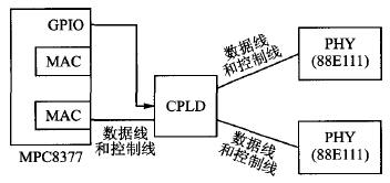
Figure 1 scheme connection
3 MPC8377 Network Design
For network connectivity, the program needs to transplant Linux system to MPC8377. In order to start the system normally, design MPC8377 as NOR Flash boot mode, NOR Flash by programming custom Uboot boot boot files, custom Linux image image files, dtb files, and Rootfs file system. After the Linux system is transplanted, the underlying network program can be completed by porting the network driver. Therefore, only the underlying driver can obtain the network diagnostic information and send the corresponding switch command to the CPLD.
3.1 Linux System Network Diagnostics
To implement a network handover procedure, it is necessary to accurately determine the network on-off state and send a handover command in time. The network is switched off by reading register 1 of the 88E111, which is the status register. The 88E111 status register is listed in Table 1.
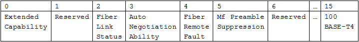
It can be seen that the status register has 16 bits, the second bit is Link status, and the third bit is auto-negotiation. The default value of the register after the Linux system starts up (default is the network is normal during Linux system startup) is 0x796D. The network status can be obtained by reading and analyzing the 2nd bit of the status register, that is, the bit is 1, indicating that the connection is normal, and 0 indicates that the connection is interrupted.
The Linux user space application can obtain the PHY address by first creating a socket socket (PF_LOCAL, SOCK_DGRAM, 0) in the user space, and then calling the ioctl (sockfd, S10CGMIIPHY, & ifr) function; by first calling (uintl6_t) strtoul('eth0') 'NULL, 0), select the network, and then call ioctl (sockfd, SIOCGMIIREG, & ifr) can access the network connection state, and finally through the if (mii a> val_out8 & 0x0004) to determine the network connection state.
3.2 GPIO driver design
Linux system drivers are divided into three categories: character devices, block devices, and network devices. This article uses character drivers to write GPIO drivers. The structure of the GPIO module is shown in Figure 2.
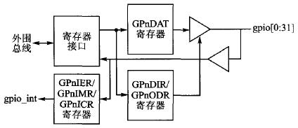
Figure 2 GPIO module structure diagram
The driver registers and unregisters the GPIO driver through module_init(GPIO_init) and module_exit(GPIO_exit), and initializes the SICRL, GPnDIR, GPnODR, and GPnDAT registers when the device driver is registered. To facilitate driver-driven device opening in user space, write GPIO driver by class_create(THIS_MODULE,"GPIO") and device create(firstdrv_class,NULL,MKDEV(major,0),NULL,"GPIO") function. The system automatically creates device nodes. Eventually the GPnDAT is overwritten by the user-space ioctl function to complete the control of the switching signal.
The Linux system starts the initialization of the PHY chip during the Uboot loading phase. In order to ensure that the system can be directly used after switching to the standby PHY after entering the Linux system, the Uboot boot initialization program needs to be changed. After the main PHY chip is initialized, the signal is switched to the spare PHY and the PHY is initialized again. The MPC8377 has a serial port. During the Uboot boot process, the Uboot boot information can be sent back to the host computer through the string El. After the Uboot initialization is completed, the serial port output is shown in Figure 3.
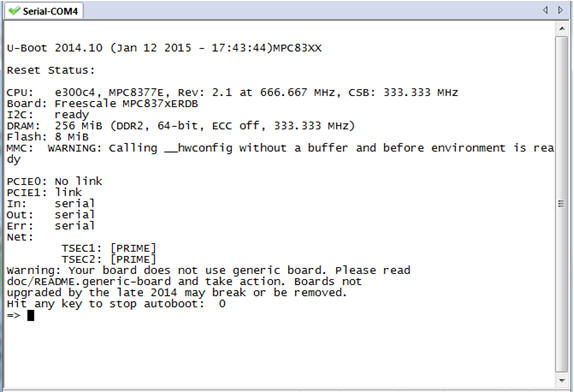
Figure 3 The MPC8377 Uboot Boot Program Initializes the Primary and Standby PHYs
As shown in Figure 3, under Net, TSEC1 and TSEC2 correspond to the initialization of the main and standby PHYs. Between the two initializations, the MPC8377 controls the GPIO pins and adjusts the connection between the MAC and the PHY through the CPLD.
3.3 program since the start and drive loading
In order to enable the user to switch programs and drivers to run automatically after the Linux system is started, the compiled user program and driver are placed in the rootfs file system and are burned and written to the N0R Flash. The GPIO driver must be started before the user program can run normally. When the Linux system starts, it will automatically load the /etc/profile file. In order to automatically start the user program and GPIO driver, you need to add the following code in the /ect/profile file:
Ifconfig eth0 192.168.81.238 netmask 255.255.255.0 //Change the network card configuration
Mkdir/lib/modules/3.0.0 //Create node for uninstalling GPIO driver
Insmod GPIO. Ko //Install GPIO driver
./main // Start the user program
4 CPLD switching design
The CPLD connects the MAC signal from the MPC8377 and passes its signal through two to two PHYs. In the Uboot boot process by the MPC8377 through the GPIO signal sent to the CPLD, so as to achieve two PHY initialization, after the start of the Linux system, MPC8377 can still be scheduled through the network state CPLD to connect different PHY.
4.1 Connection between CPLD and PHY
In addition to the MDIO signal, the I/O signals connected between the CPLD and the MAC can be directly divided by two. The resulting CPLD module is shown in FIG. 4 .
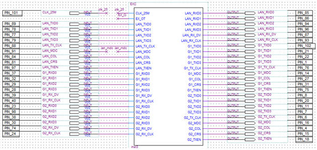
Figure 4: Two points from the MAC signal to the PHY signal in the CPLD
4.2 The MDIO design of CPLD
The MDIO signal that the MAC and PHY are connected to is a bidirectional I/O signal and cannot be directly divided into two. This article in the CPLD to determine the send and receive conditions to achieve control port I / O state switching.
The MDIO signal protocol read and write signal timings are shown in Figure 5 and Figure 6, respectively.
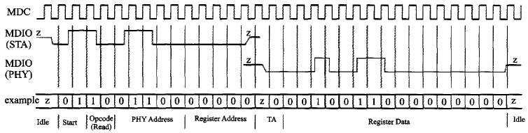
Figure 5 MDIO read timing
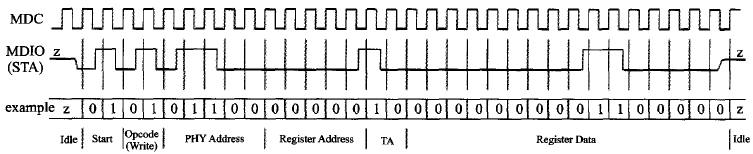
Figure 6 MDIO write timing
A second part of the MDIO can be implemented through the inout port of the CPLD. The control of the inout port can be accomplished by analyzing the timing of the MDIO. From the MDIO read and write timing (Figure 5 and Figure 6) we can see that after the Start signal, there will be read and write control bit signals, 10 is read, 01 is write, change the inout by analyzing the two bits The input and output characteristics of the port, that is, in the discovery of 10, inout appears as an input in the TA stage, and when the 01 signal is found, it appears as an output in the TA stage, and then the MDIO submodule is obtained as shown in FIG.
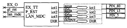
Figure 7 MDIO is divided into two modules
5 test
To obtain the switching time, call gettimeofday(&tvpre,&tz) before the network switching to obtain the current system time, and then call gettimeofday(&tvafter,&tz) to obtain the system time again after the network switching is completed and the network is connected. Finally, calculate the difference to print the master and backup switches. Time, as shown in Figure 8.
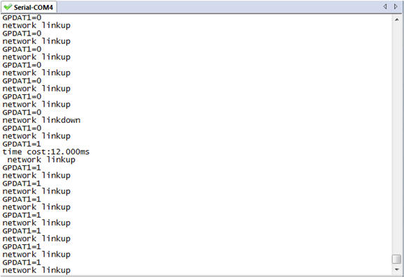
Figure 8 active and standby switching time
It can be seen through the test that the switching from PHY1 to PHY2 can be completed within only 12 ms. Through multiple tests, the switching time of the dual network remains less than 20 ms.
Conclusion
This article introduces the MPC8377 and CPLD, 88E111, through the Linux system to achieve dual-redundant network switching hot standby program, describes the preparation of the MPC8377 character device driver, and CPLD in the processing of MDIO signal applications, and ultimately make the design program can be less than 20 ms Switching time. Through the application of this solution, the reliability of the network and the duration of network recovery can be met to some extent.
Nowadays, the function and appearance of mobile phones are similar, but the charging interface is not unified. The Android camp has Micro USB and Type-C ports, while the iPhone camp has Lightning. Different charging ports use different charging cables, which is very unfriendly for users who often need to use multiple phones. To solve this awkward situation, the three-in-one data cable was born. What is the three-in-one data cable? Three-in-one data cable means that one data cable includes Micro Usb Cable, USB Cable For Iphone and Usb Cable Type C. So one data cable can be used by all mobile phones.
Three-in-one data line is also known as multifunctional data cable. In the original data cable, the combination scheme is added, and the combination PCB is configured, which can support a variety of equipment and avoid the trouble of frequently looking for data line. It combines Lightning, a 30-pin port, and a Micro USB port, and is compatible with multiple devices. It can connect to any smartphone or tablet, including iPhone, iPad, Samsung, etc.
From the technical point of view, the three-in-one data cable does have a strong advantage. With continuous development and improvement, three in one data cable products in the original data cable appearance with woven cloth, will also add a light color on the three in one data cable, so that the data cable function is stronger and more exquisite, more and more people accept and buy. In the era of big data,the 3 In 1 Usb Cable can be said to have deeply affected our work and life. We believe that with the technical development of 3-in-1 mobile phone data cable, it will bring us more convenient transmission experience.

3 In 1 Usb Cable,3 In 1 Data Cable,3 In 1 Usb C Cable,3 In 1 Universal Cable
Henan Yijiao Trading Co., Ltd , https://www.yijiaousb.com